
| | CAUTION—SHOCK HAZARD: If you are accessing the system board or installing optional hardware or memory devices sometime after setting up the printer, then turn the printer off, and unplug the power cord from the wall outlet before continuing. If you have any other devices attached to the printer, then turn them off as well, and unplug any cables going into the printer. |
You can customize your printer connectivity and memory capacity by adding optional cards. The instructions in this section explain how to install the available cards; you can also use them to locate a card for removal.
Memory cards
Printer memory
Flash memory
Fonts
Firmware cards
Bar Code and Forms
IPDS and SCS/TNe
PrintCryptionTM
PRESCRIBE
Printer hard disk
LexmarkTM Internal Solutions Ports (ISP)
RS-232-C Serial ISP
Parallel 1284-B ISP
MarkNetTM N8150802.11 b/g/n Wireless ISP
MarkNet N8130 10/100 Fiber ISP
MarkNet N8120 10/100/1000 Ethernet ISP
MarkNet N8110 V-34 Fax Card
| Note: This operation requires a flathead screwdriver. |
| | CAUTION—SHOCK HAZARD: If you are accessing the system board or installing optional hardware or memory devices sometime after setting up the printer, then turn the printer off, and unplug the power cord from the wall outlet before continuing. If you have any other devices attached to the printer, then turn them off as well, and unplug any cables going into the printer. |
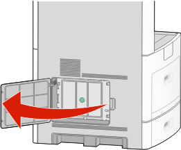
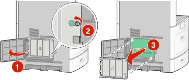
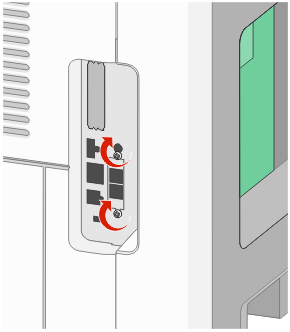
Open the system board door.
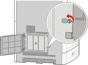
Loosen the screw(s) on the system board cover.
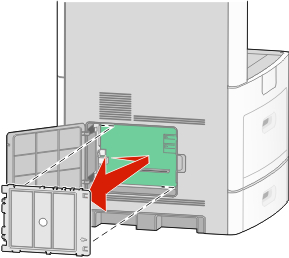
Remove the system board cover.
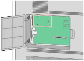
Use the illustration below to locate the appropriate connector.
| Warning—Potential Damage: System board electronic components are easily damaged by static electricity. Touch something metal on the printer before touching any system board electronic components or connectors. |
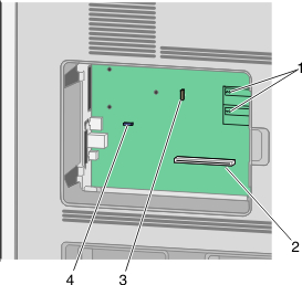
1 | Firmware and flash memory card connectors |
2 | Memory card connector |
3 | Lexmark Internal Solutions Port or printer hard disk connector |
4 | Fax card connector |
| Note: This task requires a flathead screwdriver. |
| | CAUTION—SHOCK HAZARD: If you are accessing the system board or installing optional hardware or memory devices sometime after setting up the printer, then turn the printer off, and unplug the power cord from the wall outlet before continuing. If you have any other devices attached to the printer, then turn them off as well, and unplug any cables going into the printer. |
| Warning—Potential Damage: System board electronic components are easily damaged by static electricity. Touch something metal on the printer before touching any system board electronic components or connectors. |
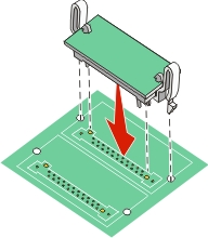
An optional memory card can be purchased separately and attached to the system board. To install the memory card:
Access the system board.
Unpack the memory card.
| Note: Avoid touching the connection points along the edge of the card. |
Open the memory card connector latches.

Align the notches on the memory card with the ridges on the connector.
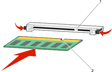
1 | Notches |
2 | Ridges |
Push the memory card straight into the connector until it snaps into place.
Replace the system board cover and close the system board door.
| Note: This task requires a flathead screwdriver. |
The system board has two connections for an optional flash memory or firmware card. Only one of each may be installed, but the connectors are interchangeable.
| | CAUTION—SHOCK HAZARD: If you are accessing the system board or installing optional hardware or memory devices sometime after setting up the printer, then turn the printer off, and unplug the power cord from the wall outlet before continuing. If you have any other devices attached to the printer, then turn them off as well, and unplug any cables going into the printer. |
| Warning—Potential Damage: System board electronic components are easily damaged by static electricity. Touch something metal on the printer before touching any system board electronic components or connectors. |
Access the system board.
Unpack the card.
| Note: Avoid touching any electrical components on the card. |
Holding the card by its sides, align the plastic pins on the card with the holes on the system board.
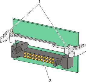
1 | Plastic pins |
2 | Metal pins |
Push the card firmly into place.
Notes:
Replace the system board cover and close the system board door.
The system board supports one optional Lexmark Internal Solutions Port (ISP). Install an ISP for additional connectivity options.
| Note: This operation requires a flathead screwdriver. |
| | CAUTION—SHOCK HAZARD: If you are accessing the system board or installing optional hardware or memory devices sometime after setting up the printer, then turn the printer off, and unplug the power cord from the wall outlet before continuing. If you have any other devices attached to the printer, then turn them off as well, and unplug any cables going into the printer. |
| Warning—Potential Damage: System board electronic components are easily damaged by static electricity. Touch something metal on the printer before touching any system board electronic components or connectors. |
Access the system board.
Unpack the ISP and plastic tee.
| Note: Avoid touching the components on the card. |
Locate the appropriate connector on the system board.
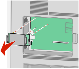
| Note: If an optional printer hard disk is currently installed, then the printer hard disk must first be removed. To remove the hard disk: |
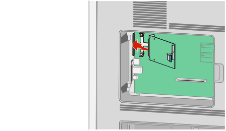
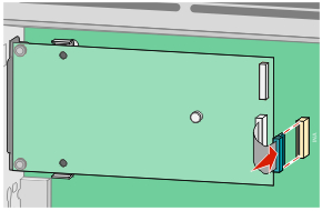
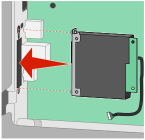
Unplug the printer hard disk interface cable from the system board, leaving the cable attached to the printer hard disk. To unplug the cable, squeeze the paddle at the plug of the interface cable to disengage the latch before pulling the cable out.
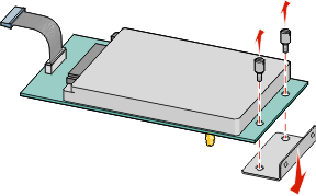
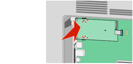
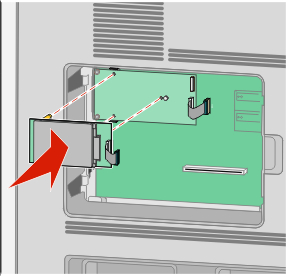
Remove the screws holding the printer hard disk in place.
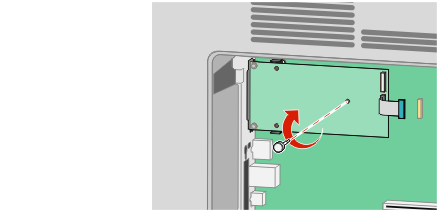
Remove the printer hard disk by pulling it upward to unseat the standoffs.
Remove the thumbscrews that attach the printer hard disk mounting bracket to the printer hard disk, and then remove the bracket. Set the printer hard disk aside.
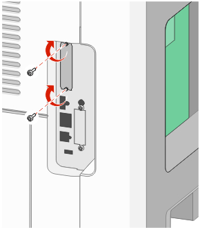
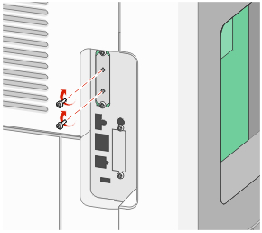
Remove the metal cover from the ISP opening.
Align the posts of the plastic tee to the holes in the system board, and then press downward until the tee snaps into place. Be sure each post of the tee has latched completely, and that the tee is seated firmly onto the system board.
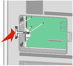
Install the ISP onto the plastic tee. Angle the ISP over the plastic tee, and then approach the plastic tee so that any overhanging connectors will pass through the ISP opening in the system board cage.
Lower the ISP toward the plastic tee until the ISP is seated between the guides of the plastic tee.
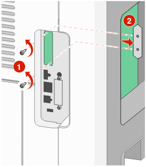
Insert the long thumbscrew and turn it clockwise enough to hold the ISP in place, but do not tighten the thumbscrew at this time.
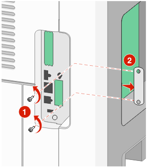
Attach the two provided screws to secure the ISP mounting bracket to the system board cage.
Tighten the long thumbscrew.
| Note: Do not overtighten the thumbscrew. |
Insert the plug of the ISP interface cable into the receptacle of the system board.
| Note: The plugs and receptacles are color coded. |
If a printer hard disk was previously installed, then attach the printer hard disk to the ISP. For more information, see Installing a printer hard disk.
Replace the system board cover and close the system board door.
The optional printer hard disk can be installed with or without a Lexmark Internal Solutions Port (ISP).
| Note: This operation requires a flathead screwdriver. |
| | CAUTION—SHOCK HAZARD: If you are accessing the system board or installing optional hardware or memory devices sometime after setting up the printer, then turn the printer off, and unplug the power cord from the wall outlet before continuing. If you have any other devices attached to the printer, then turn them off as well, and unplug any cables going into the printer. |
| Warning—Potential Damage: System board electronic components are easily damaged by static electricity. Touch something metal on the printer before touching any system board electronic components or connectors. |
Access the system board.
Unpack the printer hard disk.
| Note: Avoid touching the components on the card. |
Locate the appropriate connector on the system board.
| Note: If an optional ISP is currently installed, then the printer hard disk must be installed onto the ISP. |
To install a printer hard disk onto the ISP:
Using a flathead screwdriver to loosen the screws, remove the thumbscrews that attach the printer hard disk mounting bracket to the printer hard disk, and then remove the bracket.
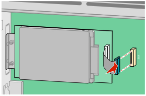
Align the standoffs of the printer hard disk with the holes in the ISP, and then press downward on the printer hard disk until the standoffs have seated into place.
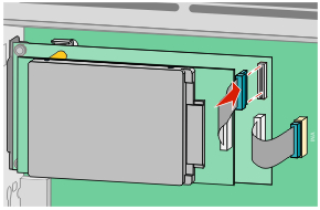
Insert the plug of the printer hard disk interface cable into the receptacle of the ISP.
| Note: The plugs and receptacles are color coded. |
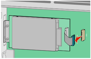
To install a printer hard disk directly onto the system board:
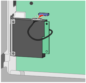
Align the standoffs of the printer hard disk with the holes in the system board, and then press downward on the printer hard disk until the standoffs have seated into place.
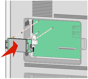
Attach the two provided screws to secure the printer hard disk mounting bracket.
Insert the plug of the printer hard disk interface cable into the receptacle of the system board.
| Note: The plugs and receptacles are color coded. |
Replace the system board cover and close the system board door.
| Note: This task requires a flathead screwdriver. |
| | CAUTION—SHOCK HAZARD: If you are accessing the system board or installing optional hardware or memory devices sometime after setting up the printer, then turn the printer off, and unplug the power cord from the wall outlet before continuing. If you have any other devices attached to the printer, then turn them off as well, and unplug any cables going into the printer. |
| Warning—Potential Damage: System board electronic components are easily damaged by static electricity. Touch something metal on the printer before touching any system board electronic components or connectors. |
Access the system board.
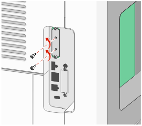
Unpack the fax card.
Remove the metal cover from the fax card opening.
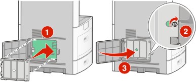
Insert the fax card and attach the two provided screws to secure the fax card mounting bracket.
Insert the plug of the fax card interface cable into the receptacle of the system board.
Replace the system board cover and close the system board door.