Accessing the controller board
 CAUTION—SHOCK HAZARD:
 To avoid the risk of electrical shock, if you are accessing the controller board or installing optional hardware or memory devices sometime after setting up the printer, then turn the printer off, and unplug the power cord from the electrical outlet before continuing. If you have any other devices attached to the printer, then turn them off as well, and unplug any cables going into the printer.
Turn off the printer.
Unplug the power cord from the electrical outlet, and then from the printer.
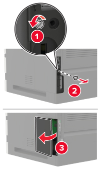
Using a flat-head screwdriver, open the controller board access cover.
Warning—Potential Damage: Controller board electronic components are easily damaged by static electricity. Touch a metal surface on the printer before touching any controller board components or connectors.
Install any supported internal options. For more information, see the documentation that came with the option.
Close the access cover.
Connect the power cord to the printer, and then to the electrical outlet.
 CAUTION—POTENTIAL INJURY:
 To avoid the risk of fire or electrical shock, connect the power cord to an appropriately rated and properly grounded electrical outlet that is near the product and easily accessible.
Turn on the printer.
Installing a memory card
CAUTION—SHOCK HAZARD: To avoid the risk of electrical shock, if you are accessing the controller board or installing optional hardware or memory devices sometime after setting up the printer, then turn the printer off, and unplug the power cord from the electrical outlet before continuing. If you have any other devices attached to the printer, then turn them off as well, and unplug any cables going into the printer.
Turn off the printer.
Unplug the power cord from the electrical outlet, and then from the printer.
Using a flat-head screwdriver, open the controller board access cover.
Warning—Potential Damage: Controller board electronic components are easily damaged by static electricity. Touch a metal surface on the printer before touching any controller board components or connectors.
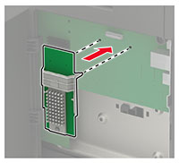
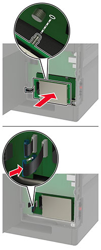
Unpack the memory card.
Warning—Potential Damage: Do not touch the connection points along the edge of the card.
Insert the memory card until it clicks into place.
Close the access cover.
Connect the power cord to the printer, and then to the electrical outlet.
CAUTION—POTENTIAL INJURY: To avoid the risk of fire or electrical shock, connect the power cord to an appropriately rated and properly grounded electrical outlet that is near the product and easily accessible.
Turn on the printer.
Installing an optional card
CAUTION—SHOCK HAZARD: To avoid the risk of electrical shock, if you are accessing the controller board or installing optional hardware or memory devices sometime after setting up the printer, then turn the printer off, and unplug the power cord from the electrical outlet before continuing. If you have any other devices attached to the printer, then turn them off as well, and unplug any cables going into the printer.
Turn off the printer.
Unplug the power cord from the electrical outlet, and then from the printer.
Using a flat-head screwdriver, open the controller board access cover.
Warning—Potential Damage: Controller board electronic components are easily damaged by static electricity. Touch a metal surface on the printer before touching any components or connectors.
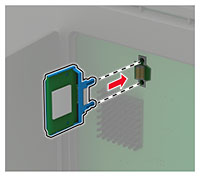
Unpack the optional card.
Warning—Potential Damage: Do not touch the connection points along the edge of the card.
Push the card firmly into place.
Note: The entire length of the connector on the card must touch and be flush against the controller board.
Warning—Potential Damage: Improper installation of the card may cause damage to the card and the controller board.
Close the access cover.
Connect the power cord to the printer, and then to the electrical outlet.
CAUTION—POTENTIAL INJURY: To avoid the risk of fire or electrical shock, connect the power cord to an appropriately rated and properly grounded electrical outlet that is near the product and easily accessible.
Turn on the printer.
Installing a printer hard disk
CAUTION—SHOCK HAZARD: To avoid the risk of electrical shock, if you are accessing the controller board or installing optional hardware or memory devices sometime after setting up the printer, then turn the printer off, and unplug the power cord from the electrical outlet before continuing. If you have any other devices attached to the printer, then turn them off as well, and unplug any cables going into the printer.
Turn off the printer.
Unplug the power cord from the electrical outlet, and then from the printer.
Using a flat-head screwdriver, open the controller board access cover.
Warning—Potential Damage: Controller board electronic components are easily damaged by static electricity. Touch a metal surface on the printer before touching any controller board components or connectors.
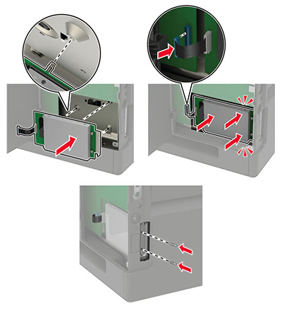
Unpack the printer hard disk.
Attach the hard disk, and then connect the hard disk interface cable to the controller board.
Warning—Potential Damage: Do not touch or press the center of the hard disk.
Close the access cover.
Connect the power cord to the printer, and then to the electrical outlet.
CAUTION—POTENTIAL INJURY: To avoid the risk of fire or electrical shock, connect the power cord to an appropriately rated and properly grounded electrical outlet that is near the product and easily accessible.
Turn on the printer.
Installing an internal solutions port
CAUTION—SHOCK HAZARD: To avoid the risk of electrical shock, if you are accessing the controller board or installing optional hardware or memory devices sometime after setting up the printer, then turn the printer off, and unplug the power cord from the electrical outlet before continuing. If you have any other devices attached to the printer, then turn them off as well, and unplug any cables going into the printer.
Turn off the printer, and then unplug the power cord from the electrical outlet.
Using a flat-head screwdriver, open the controller board access cover.
Warning—Potential Damage: Controller board electronic components are easily damaged by static electricity. Touch a metal surface on the printer before touching any controller board components or connectors.
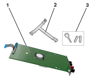
Unpack the internal solutions port (ISP) kit.
1 | ISP |
2 | Mounting bracket |
3 | Thumbscrews |
If necessary, remove the printer hard disk.
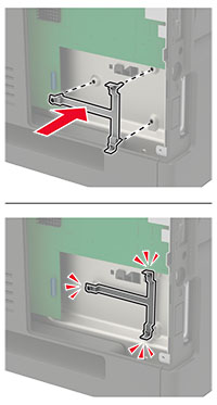
Insert the bracket into the board until it clicks into place.
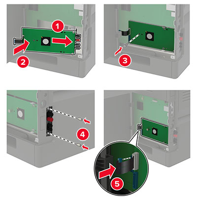
Attach the ISP to the bracket.
If necessary, attach the hard disk to the ISP.
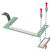
Remove the hard disk bracket.
Connect the hard disk to the ISP.
Warning—Potential Damage: Do not touch or press the center of the hard disk.
Close the access cover.
Connect the power cord to the electrical outlet, and then turn on the printer.
CAUTION—POTENTIAL INJURY: To avoid the risk of fire or electrical shock, connect the power cord to an appropriately rated and properly grounded electrical outlet that is near the product and easily accessible.
Installing the 550-sheet tray
CAUTION—SHOCK HAZARD: To avoid the risk of electrical shock, if you are accessing the controller board or installing optional hardware or memory devices sometime after setting up the printer, then turn the printer off, and unplug the power cord from the electrical outlet before continuing. If you have any other devices attached to the printer, then turn them off as well, and unplug any cables going into the printer.
 CAUTION—TIPPING HAZARD:
 Installing one or more options on your printer or MFP may require a caster base, furniture, or other feature to prevent instability causing possible injury. For more information on supported configurations, see
www.lexmark.com/multifunctionprinters.
Turn off the printer.
Unplug the power cord from the electrical outlet, and then from the printer.
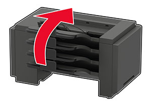
Unpack the optional tray, and then remove all packing material.
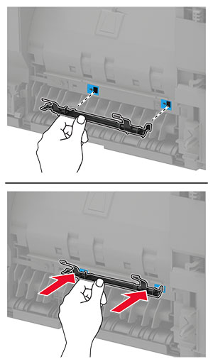
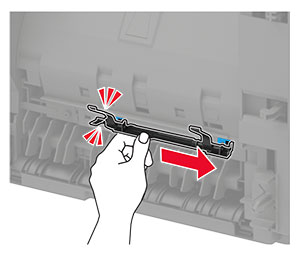
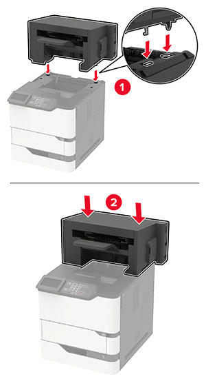
Note: If optional trays are already installed, then unlock them from the printer before lifting the printer. Do not try to lift the printer and trays at the same time.
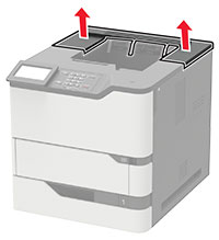
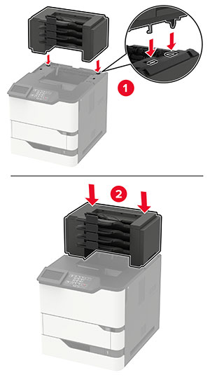
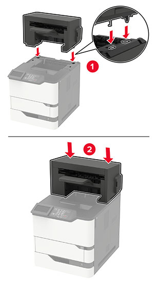
Align the printer with the optional tray, and then lower the printer until it clicks into place.
CAUTION—POTENTIAL INJURY: If the printer weight is greater than 20 kg (44 lb), then it may require two or more people to lift it safely.
Connect the power cord to the printer, and then to the electrical outlet.
CAUTION—POTENTIAL INJURY: To avoid the risk of fire or electrical shock, connect the power cord to an appropriately rated and properly grounded electrical outlet that is near the product and easily accessible.
Turn on the printer.
Add the tray in the print driver to make it available for print jobs. For more information, see Adding available options in the print driver.
Installing the 2100-sheet tray
CAUTION—SHOCK HAZARD: To avoid the risk of electrical shock, if you are accessing the controller board or installing optional hardware or memory devices sometime after setting up the printer, then turn the printer off, and unplug the power cord from the electrical outlet before continuing. If you have any other devices attached to the printer, then turn them off as well, and unplug any cables going into the printer.
CAUTION—TIPPING HAZARD: Installing one or more options on your printer or MFP may require a caster base, furniture, or other feature to prevent instability causing possible injury. For more information on supported configurations, see
www.lexmark.com/multifunctionprinters.
Turn off the printer.
Unplug the power cord from the electrical outlet, and then from the printer.
Unpack the tray, and then remove all packing material.
Note: If optional trays are already installed, then unlock them from the printer before lifting the printer. Do not try to lift the printer and trays at the same time.
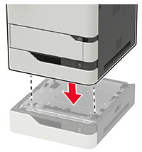
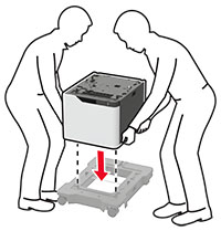
Install the tray on the caster base.
Note: Make sure that the caster base wheels are locked.
CAUTION—POTENTIAL INJURY: If the tray weight is greater than 20 kg (44 lb), then it may require two or more people to lift it safely.
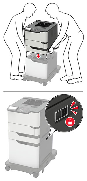
Align the printer with the tray, and then lower the printer until it clicks into place.
CAUTION—POTENTIAL INJURY: If the printer weight is greater than 20 kg (44 lb), then it may require two or more people to lift it safely.
Connect the power cord to the printer, and then to the electrical outlet.
CAUTION—POTENTIAL INJURY: To avoid the risk of fire or electrical shock, connect the power cord to an appropriately rated and properly grounded electrical outlet that is near the product and easily accessible.
Turn on the printer.
Add the tray in the print driver to make it available for print jobs. For more information, see Adding available options in the print driver.