CAUTION—SHOCK HAZARD:
To avoid the risk of electrical shock, if you are accessing the controller board or installing optional hardware or memory devices sometime after setting up the printer, then turn the printer off, and unplug the power cord from the electrical outlet before continuing. If you have any other devices attached to the printer, then turn them off as well, and unplug any cables going into the printer.
-
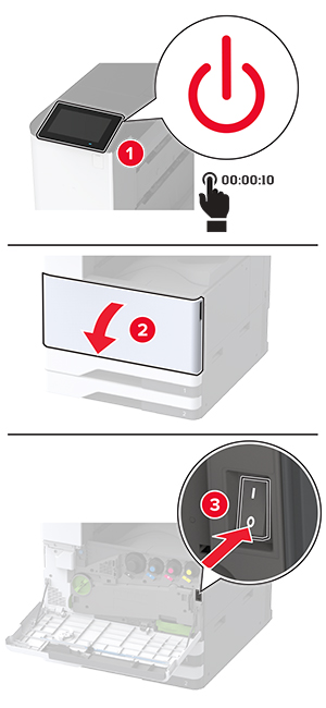
Turn off the printer.
-
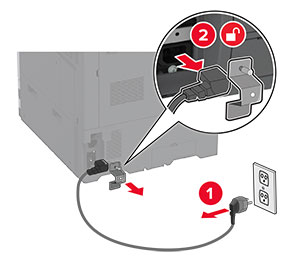
Unplug the power cord from the electrical outlet, and then from the printer.
-
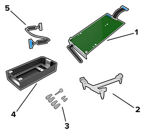
Unpack the booklet finisher, and then remove all the packing material.
-
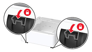
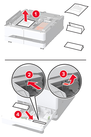
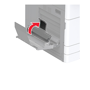
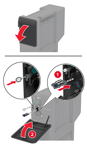
Open the booklet finisher door.
-
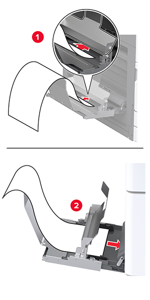
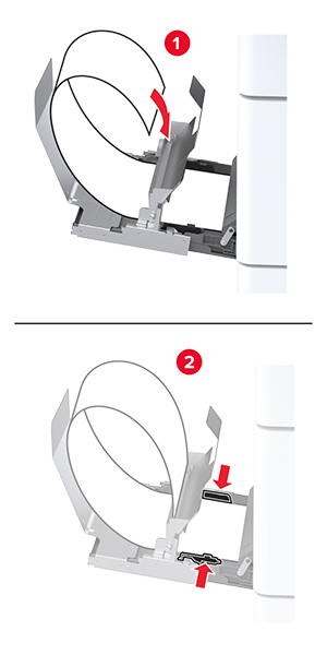
Remove the packing material inside the booklet finisher.
-
Insert the staple cartridge holder.
-
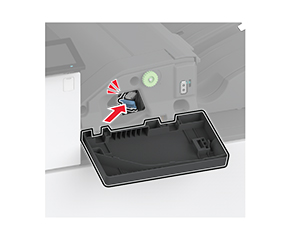
Insert the hole punch box.
-
Close the booklet finisher door.
-
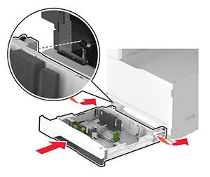
Insert the bins.
-
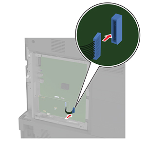
Insert the booklet finisher cable.
-
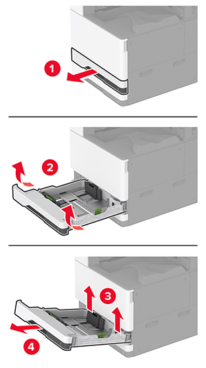
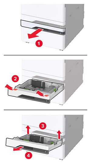
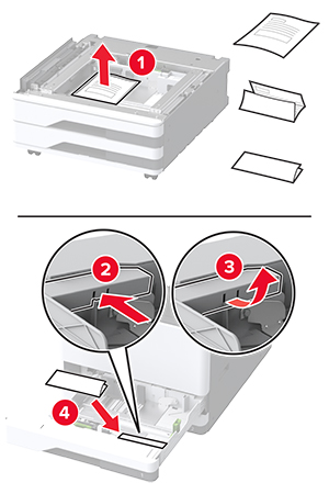
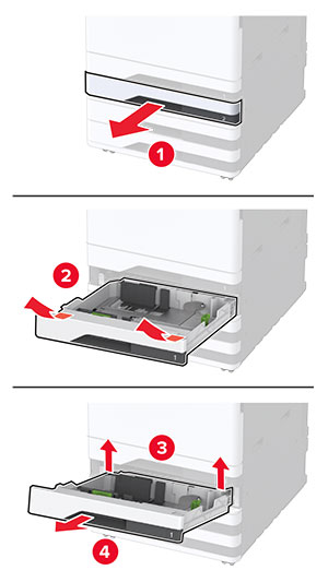
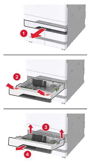
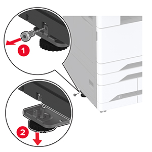
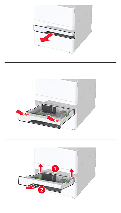
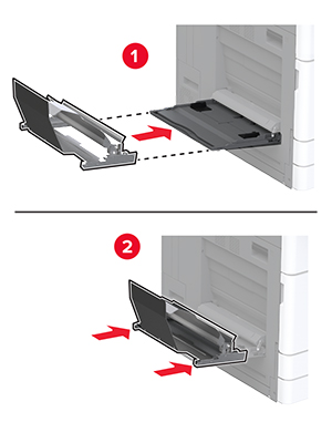
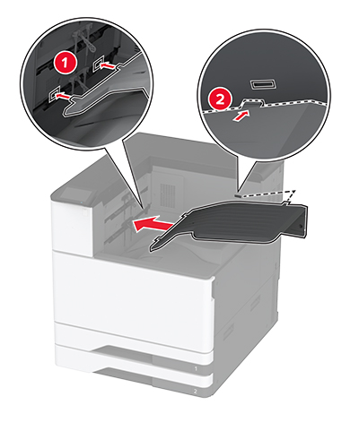
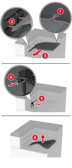
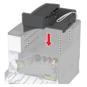
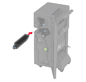
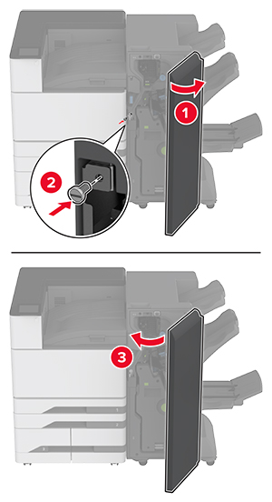
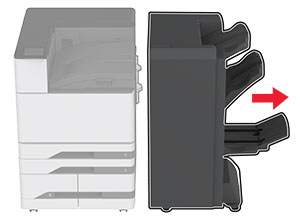
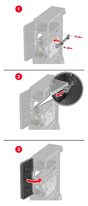
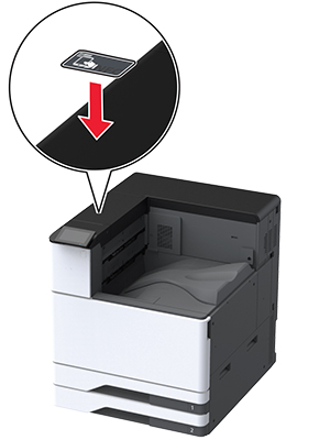
Remove the standard bin.
Note:
Do not throw away the standard bin.
-
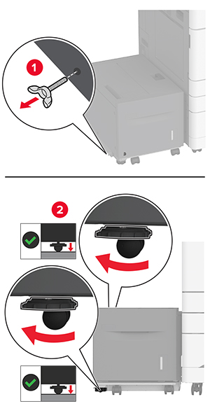
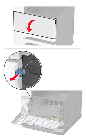
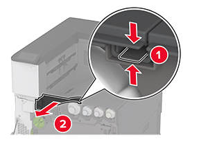
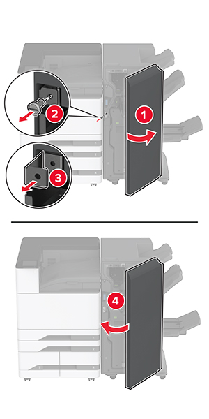
Open the front door, and then remove the blue knob.
Note:
Do not throw away the knob.
-
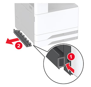
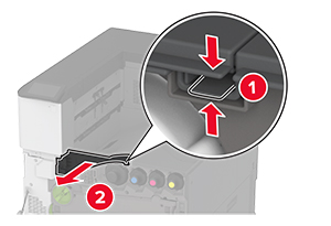
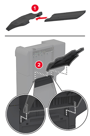
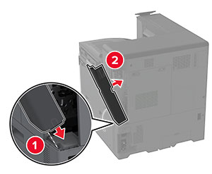
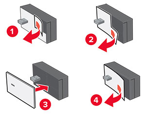
Remove the standard bin side cover.
Note:
Do not throw away the bin side cover.
-
Close the front door.
-
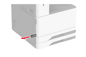
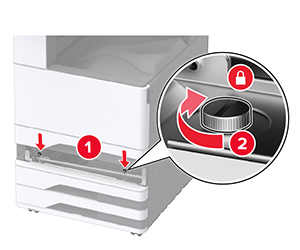
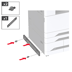
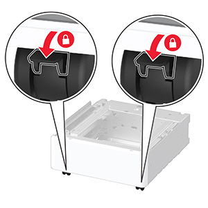
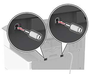
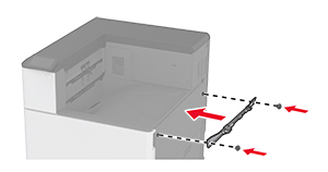
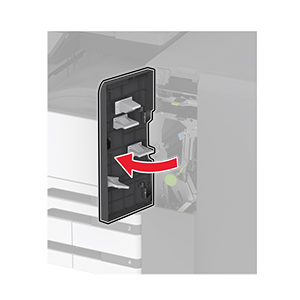
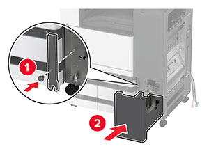
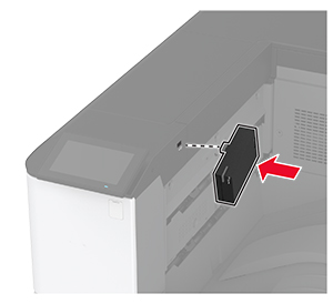
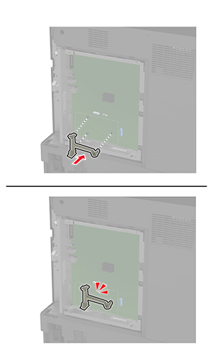
Attach the installation bracket for the finisher.
-
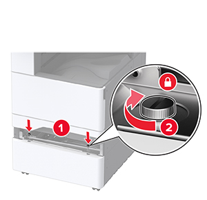
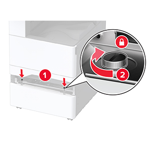
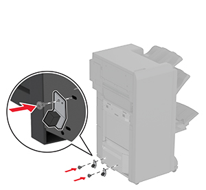
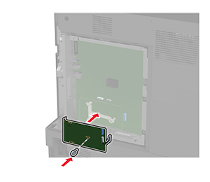
Insert the paper transport, and then use the screws to secure it.
Note:
Use the screws that came with the finisher.
-
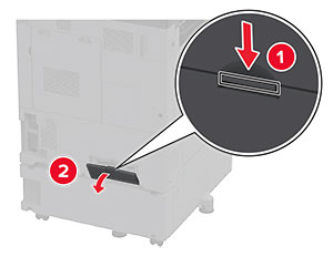
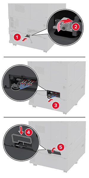
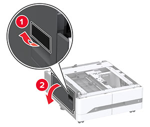
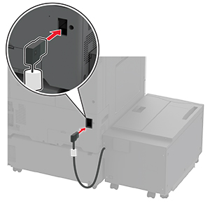
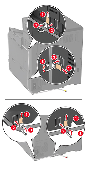
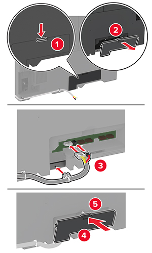
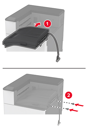
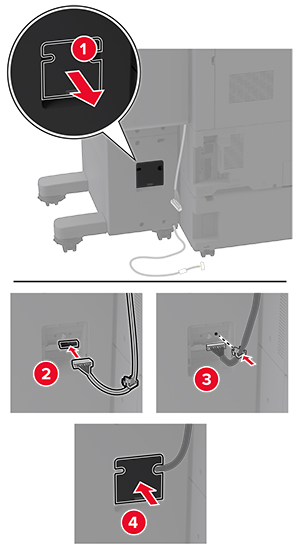
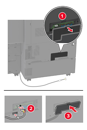
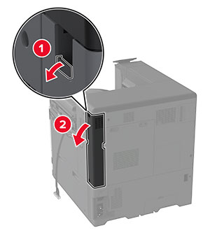
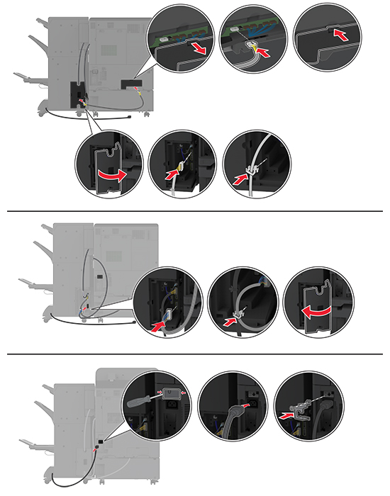
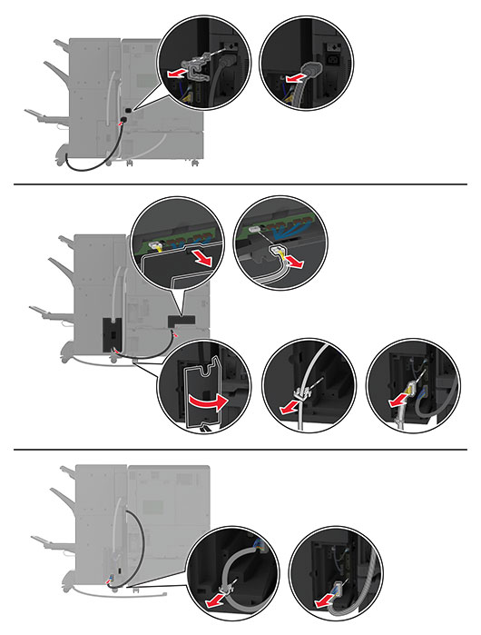
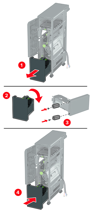
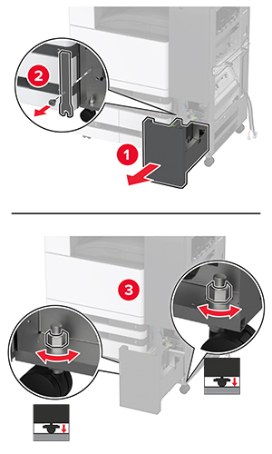
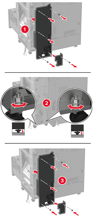
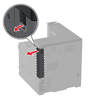
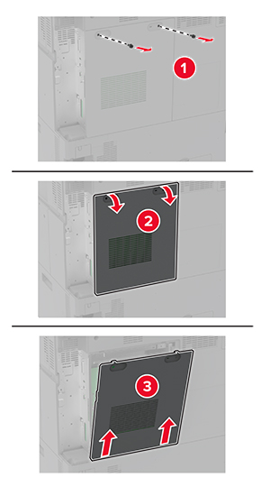
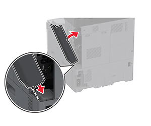
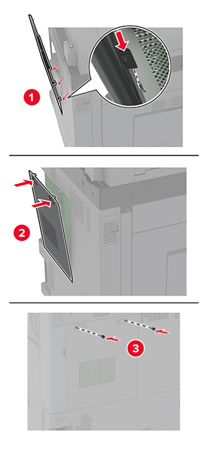
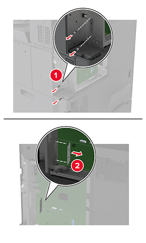
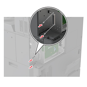
Remove the rear ports cover.
-
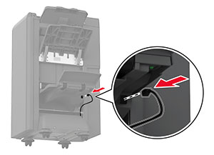
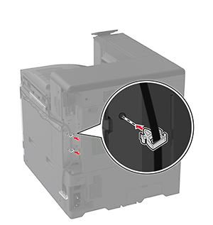
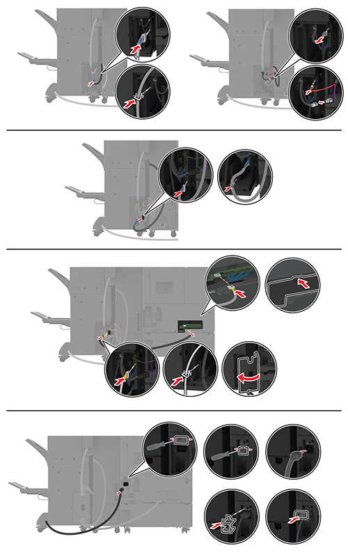
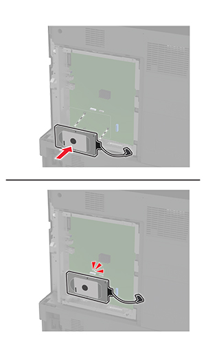
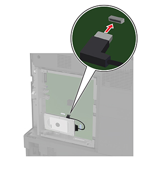
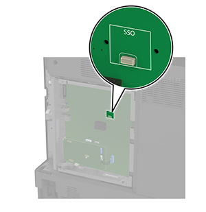
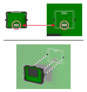
Secure the cable.
-
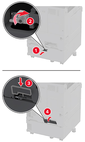
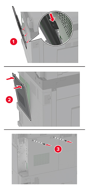
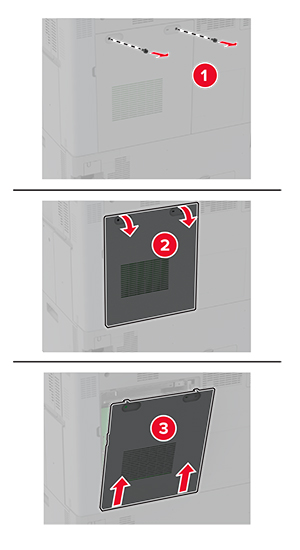
Attach the rear ports cover.
-
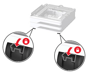
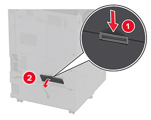
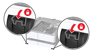
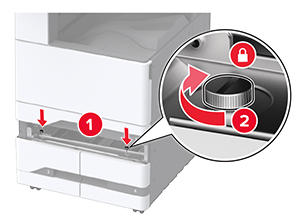
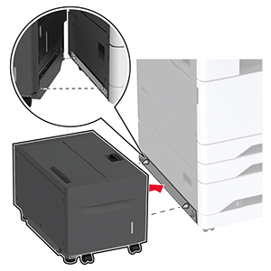
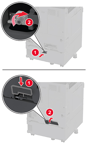
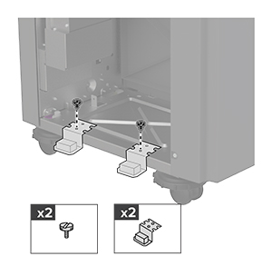
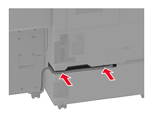
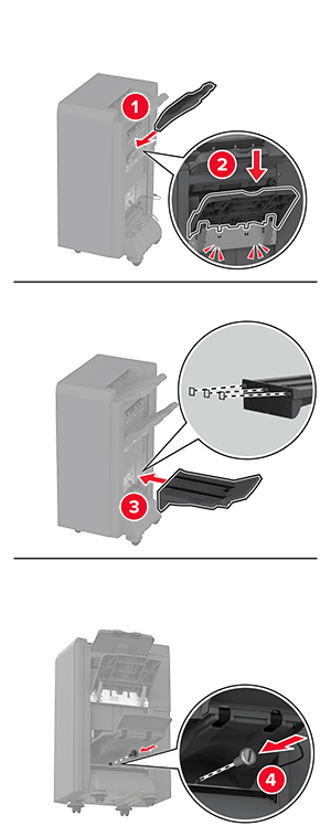
Attach the brackets at the bottom of the finisher.
-
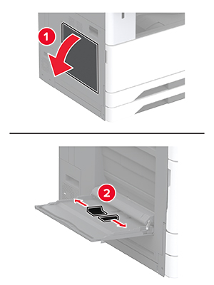
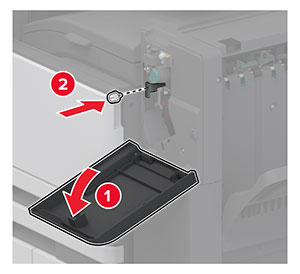
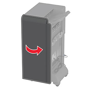
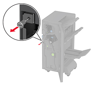
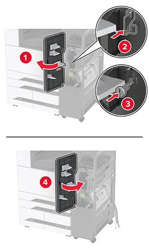
Open the booklet finisher door.
-
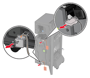
Using a flat-head screwdriver, remove the screw, and then close the finisher door.
-
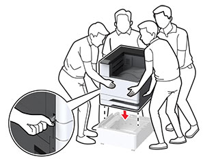
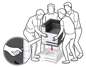
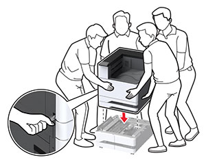
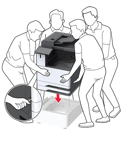
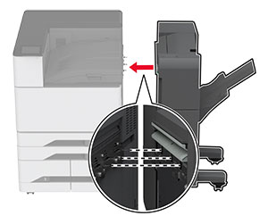
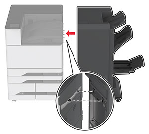
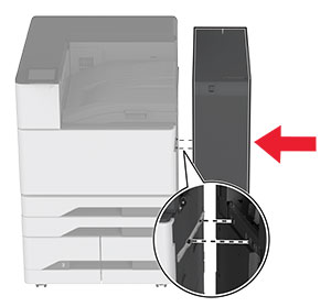
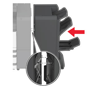
Attach the finisher to the printer.
-
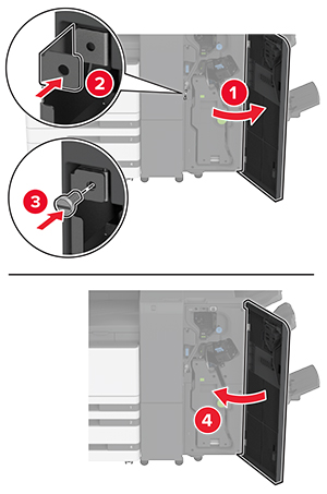
Open the finisher door, use the screw to secure the finisher to the printer, and then close the door.
-
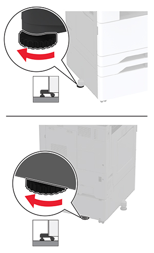
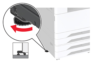
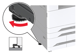
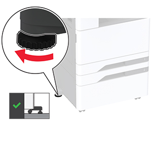
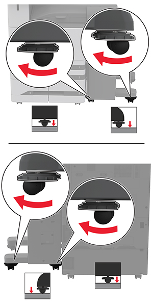
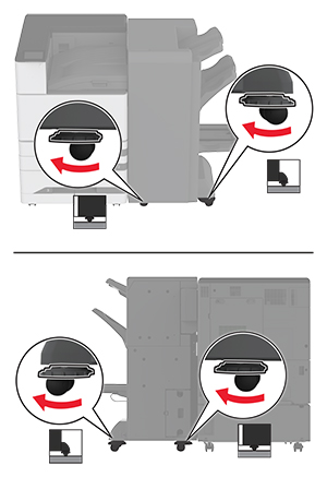
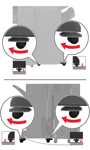
Rotate the side wheels of the finisher clockwise to make sure that all sides of the finisher have the same height.
-
Connect the cables to the printer ports and finisher ports.
-
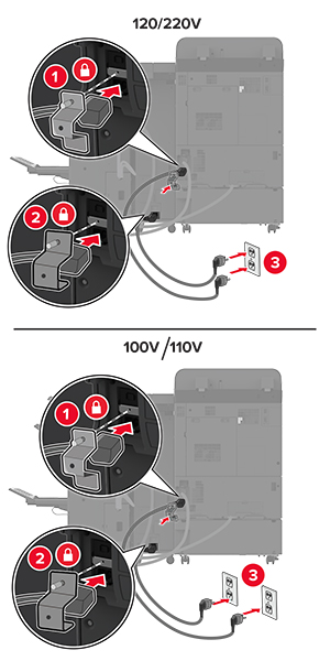
Connect the power cord to the printer, and then to the electrical outlet.
 CAUTION—POTENTIAL INJURY:
To avoid the risk of fire or electrical shock, connect the power cord to an appropriately rated and properly grounded electrical outlet that is near the product and easily accessible.
-
Turn on the printer.