Replacing parts and supplies
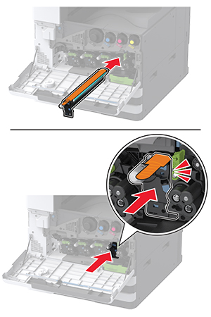
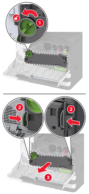
Replacing a toner cartridge
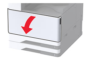
-
Open the front door.
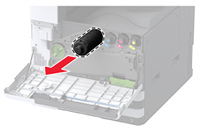
-
Remove the used toner cartridge.
-
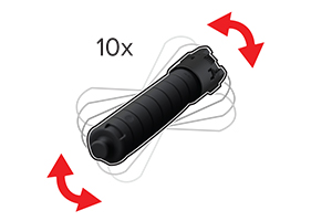
Unpack the new toner cartridge.
-
Shake the toner cartridge to redistribute the toner.
-
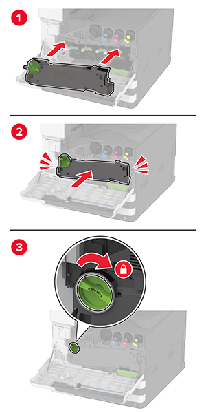
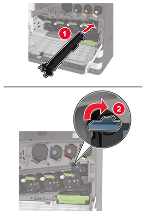
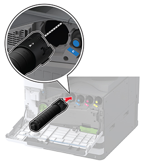
Insert the new toner cartridge.
-
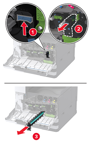
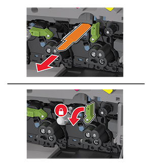
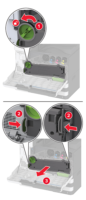
Remove the waste toner transfer unit.
Note:
To avoid spilling the toner, place the unit in an upright position.
-
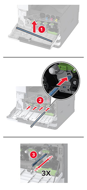
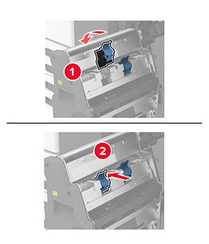
Remove the printhead wiper, and then clean the printhead lenses.
-
Put the printhead wiper back into place.
-
Insert the waste toner transfer unit until it
clicks
into place, and then lock it.
-
Close the door.
Replacing a photoconductor unit
-
Open the front door.
-
Remove the waste toner transfer unit.
Note:
To avoid spilling the toner, place the unit in an upright position.
-
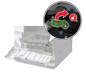
Unlock the used photoconductor unit.
-
Remove the used photoconductor unit.
-
Unpack the new photoconductor unit.
Warning—Potential Damage:
Do not expose the photoconductor unit to direct light for more than one minute. Extended exposure to light may cause print quality problems.
Warning—Potential Damage:
Do not touch the photoconductor drum. Doing so may affect the quality of future print jobs.
-
Insert the new photoconductor unit until it
clicks
into place.
-
Remove the packing material, and then lock the new photoconductor unit.
-
Remove the printhead wiper, and then clean the printhead lenses.
-
Put the printhead wiper back into place.
-
Insert the waste toner transfer unit until it
clicks
into place, and then lock it.
-
Close the door.
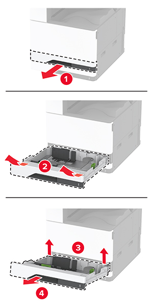
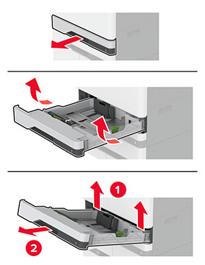
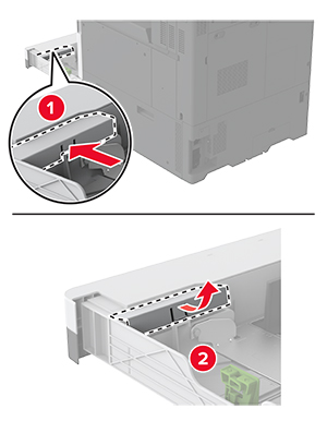
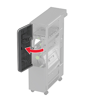
Replacing the 520-sheet tray insert
Replacing the 520-sheet tray insert
-
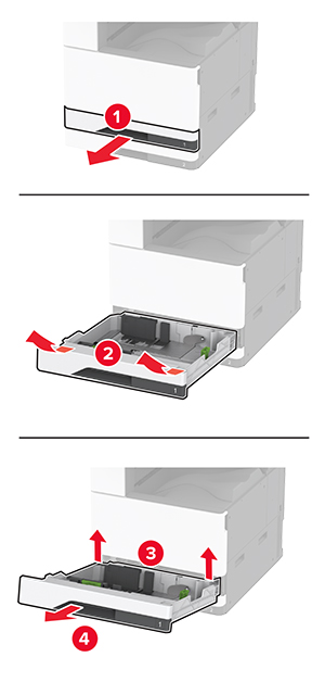
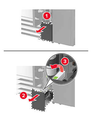
Remove the used tray insert.
-
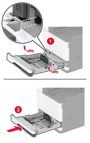
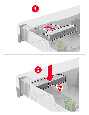
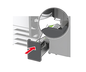
Unpack the new tray insert, and then remove all the packing material.
-
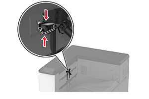
Insert the new tray insert.
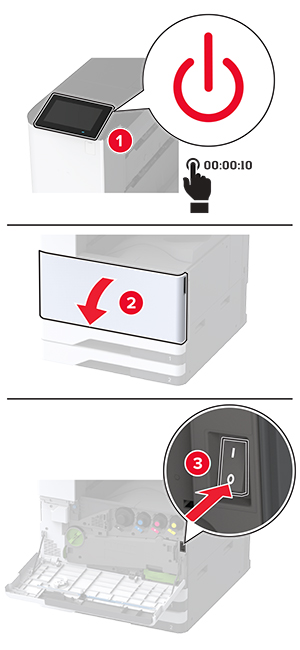
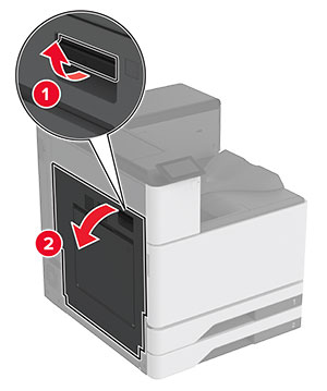
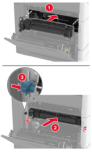
Replacing the fuser
Replacing the fuser
-
Turn off the printer.
-
Open door A.
 CAUTION—HOT SURFACE:
The inside of the printer might be hot. To reduce the risk of injury from a hot component, allow the surface to cool before touching it.
-
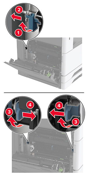
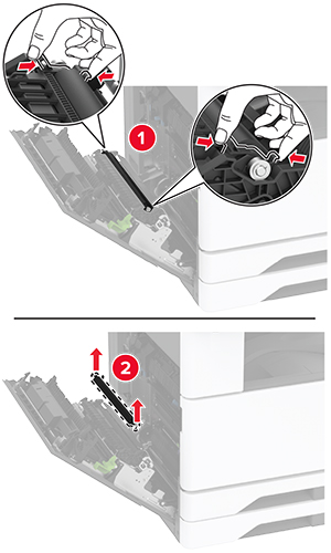
Unlock the fuser.
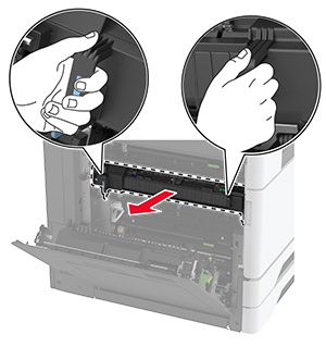
-
Remove the used fuser.
-
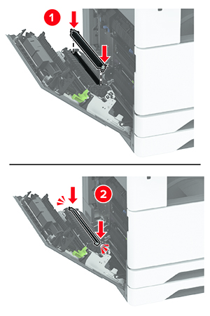
Unpack the new fuser.
-
Insert the new fuser until it
clicks
into place, and then lock it.
-
Close door A.
-
Turn on the printer.
Replacing the printhead wiper
Replacing the printhead wiper
-
Open the front door.
-
Remove the used printhead wiper.
-
Unpack the new printhead wiper.
-
Insert the new printhead wiper.
-
Close the front door.
Replacing the transfer module cleaner
-
Open the front door.
-
Remove the waste toner transfer unit.
Note:
To avoid spilling the toner, place the unit in an upright position.
-
Remove the used transfer module cleaner.
-
Unpack the new transfer module cleaner.
-
Insert the new transfer module cleaner.
-
Insert the waste toner transfer unit until it
clicks
into place, and then lock it.
-
Close the front door.
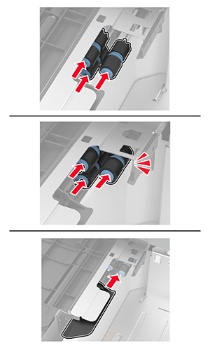
Replacing the tray roller kit
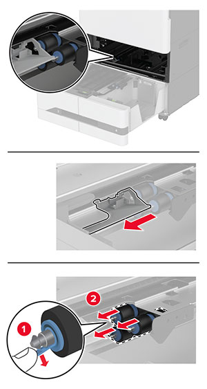
Replacing the tray roller kit
-
Turn off the printer.
-
Remove the standard tray.
-
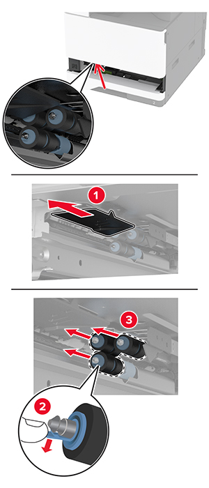
Remove the used tray roller kit.
Warning—Potential Damage:
To prevent damage from electrostatic discharge, touch any exposed metal frame of the printer before accessing or touching interior areas of the printer.
-
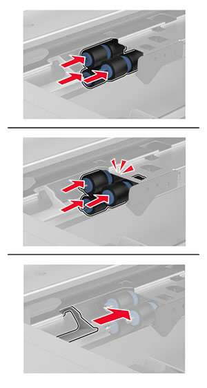
Unpack the new tray roller kit.
-
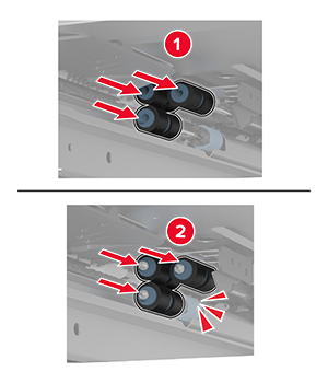
Insert the new tray roller kit until it
clicks
into place.
-
Insert the tray.
-
Turn on the printer.
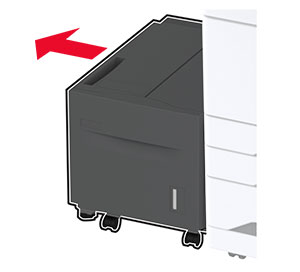
Replacing the 2000-sheet tray roller kit
Replacing the 2000-sheet tray roller kit
-
Turn off the printer.
-
Slide the tray to the left.
-
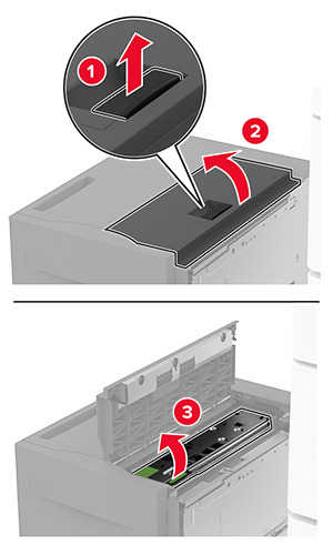
Open door J, and then open the roller kit cover.
-
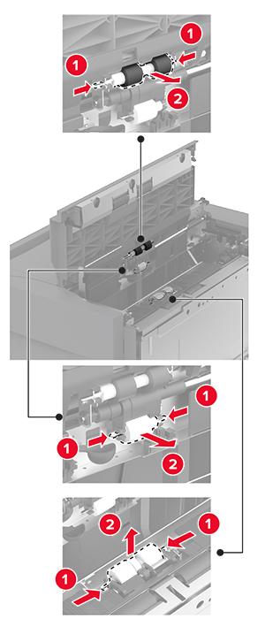
Locate and remove the used roller kit.
-
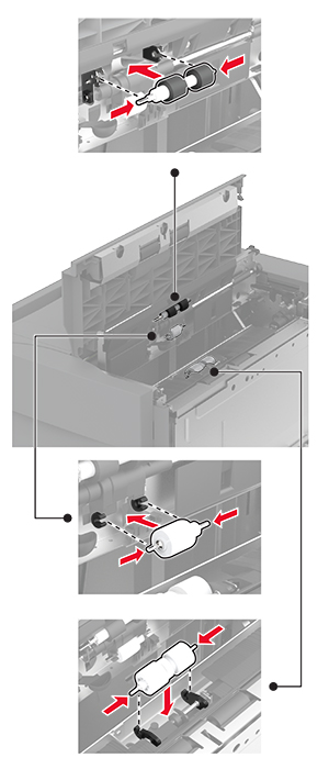
Unpack the new roller kit.
-
Insert the new roller kit.
-
Close the roller kit cover, and then close door J.
-
Slide the tray back into place.
-
Turn on the printer.
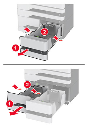
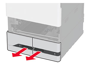
Replacing the 2000-sheet tandem tray roller kit
In handle C
-
Turn off the printer.
-
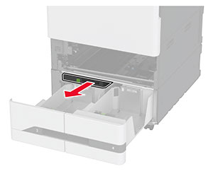
Pull out tray 4, and then pull out tray 3.
-
Pull out handle C, and then open the inner cover.
-
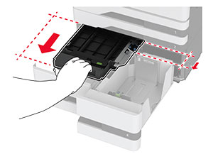
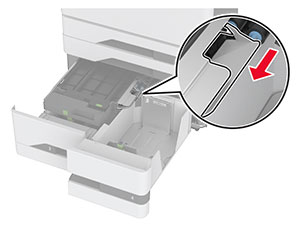
Open the roller kit cover.
-
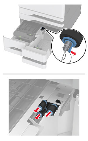
Remove the used tray roller kit.
Warning—Potential Damage:
To prevent damage from electrostatic discharge, touch any exposed metal frame of the printer before accessing or touching interior areas of the printer.
-
Unpack the new tray roller kit.
-
Insert the new tray roller kit until it
clicks
into place.
-
Close the roller kit cover.
-
Close the inner cover, and then insert handle C.
-
Insert trays 3 and 4.
-
Turn on the printer.
In tray 3
-
Turn off the printer.
-
Remove tray 1, and then remove tray 2.
-
Pull out trays 3 and 4.
-
Pull out handle C.
-
Remove the used tray roller kit.
Warning—Potential Damage:
To prevent damage from electrostatic discharge, touch any exposed metal frame of the printer before accessing or touching interior areas of the printer.
-
Insert the new tray roller kit until it
clicks
into place.
-
Insert handle C.
-
Insert trays 3 and 4.
-
Insert trays 1 and 2.
-
Turn on the printer.
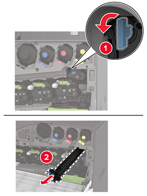
Replacing the second transfer roller
Replacing the second transfer roller
-
Turn off the printer.
-
Open door A.
CAUTION—HOT SURFACE:
The inside of the printer might be hot. To reduce the risk of injury from a hot component, allow the surface to cool before touching it.
-
Remove the used second transfer roller.
-
Unpack the new second transfer roller.
-
Insert the new second transfer roller.
-
Close the door.
-
Turn on the printer.
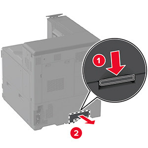
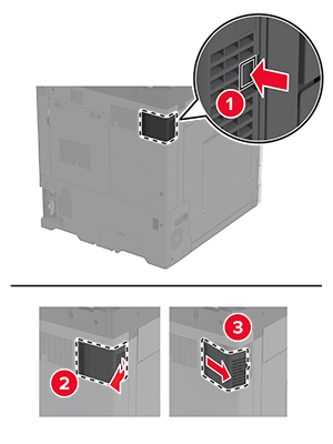
Replacing the lower rear connector cover
Replacing the lower rear connector cover
-
Remove the used lower rear connector cover.
-
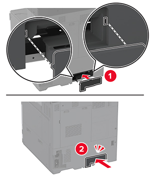
Unpack the new lower rear connector cover.
-
Insert the new lower rear connector cover until it
clicks
into place.
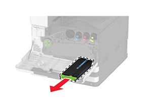
Replacing the waste toner bottle
-
Open the front door.
-
Remove the waste toner transfer unit.
Note:
To avoid spilling the toner, place the unit in an upright position.
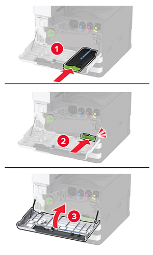
-
Remove the printhead wiper, and then clean the printhead lenses.
-
Put the printhead wiper back into place.
-
Insert the waste toner transfer unit until it
clicks
into place, and then lock it.
-
Remove the used waste toner bottle.
-
Unpack the new waste toner bottle.
-
Insert the new waste toner bottle until it
clicks
into place, and then close the door.
Replacing the waste toner transfer unit
-
Open the front door.
-
Remove the used waste toner transfer unit.
Note:
To avoid spilling the toner, place the unit in an upright position.
-
Unpack the new waste toner transfer unit.
-
Insert the new waste toner transfer unit until it
clicks
into place, and then lock it.
-
Close the front door.
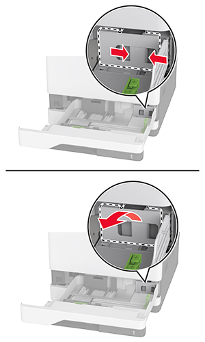
Replacing the small cover in the tray insert
Replacing the small cover in the tray insert
-
Pull out the tray.
-
Remove the used small cover.
-
Unpack the new small cover.
-
Insert the new small cover.
-
Insert the tray.
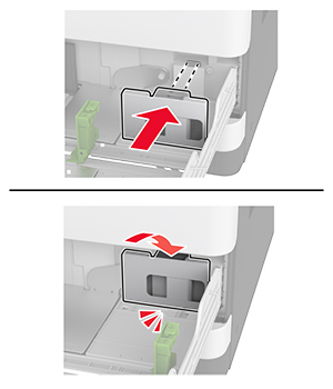
Replacing the B4 paper guide in the tray insert
Replacing the B4 paper guide in the tray insert
-
Pull out the tray.
-
Remove the used B4 paper guide.
-
Unpack the new B4 paper guide.
-
Insert the new B4 paper guide.
-
Insert the tray.
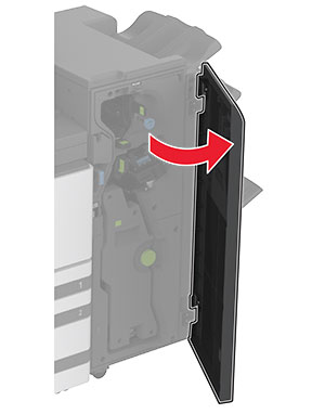
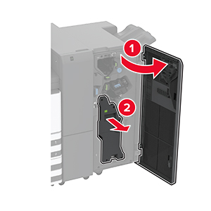
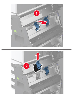
Replacing the hole punch box in the booklet finisher
Replacing the hole punch box in the booklet finisher
-
Open the booklet finisher door.
-
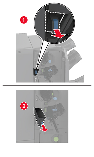
Remove the used hole punch box.
-
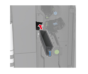
Unpack the new hole punch box.
-
Insert the new hole punch box.
-
Close the booklet finisher door.
Replacing the trifold/Z-fold finisher bin
Replacing the trifold/Z-fold finisher bin
-
Turn off the printer.
-
Open the trifold/Z-fold finisher door.
-
Remove the used finisher bin.
-
Unpack the new finisher bin.
-
Insert the new finisher bin.
-
Close the finisher door.
-
Turn on the printer.
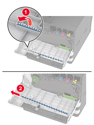
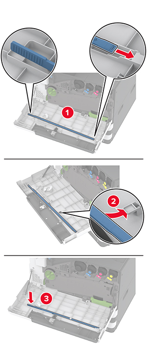
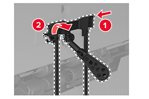
Replacing the paper bail
-
Pinch the left side of the paper bail to unlock it.
-
Remove the used paper bail.
-
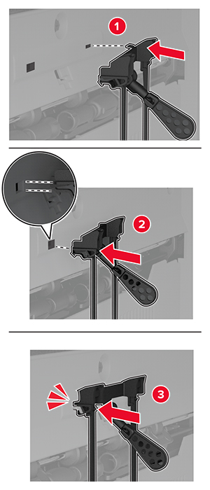
Unpack the new paper bail.
-
Insert the new paper bail until it
clicks
into place.
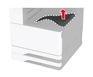
Replacing the dual catch bin
-
Remove the used dual catch bin.
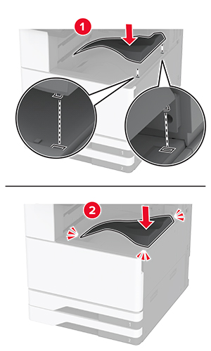
-
Unpack the new dual catch bin.
-
Attach the new dual catch bin until it
clicks
into place.
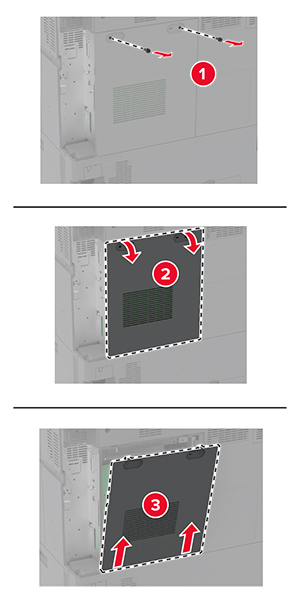
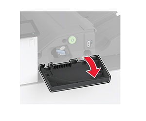
Replacing the controller board access cover
-
Remove the rear ports cover.
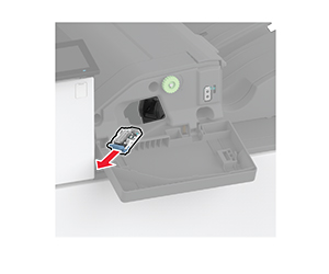
-
Using a flat-head screwdriver, remove the used controller board access cover.
-
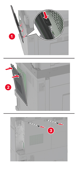
Unpack the new controller board access cover.
-
Attach the new controller board access cover.
-
Attach the rear ports cover.
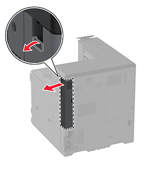
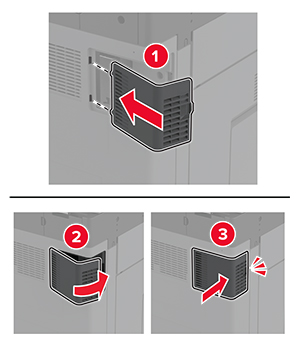
Replacing the rear ports cover
-
Remove the used rear ports cover.
-
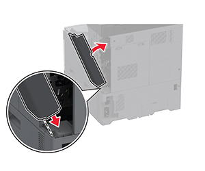
Unpack the new rear ports cover.
-
Attach the new rear ports cover.
Replacing the R9 rear cover
Replacing the R9 rear cover
-
Remove the used R9 rear cover.
-
Unpack the new R9 rear cover.
-
Attach the new R9 rear cover until it
clicks
into place.
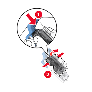
Replacing the staple cartridge unit
Replacing the staple cartridge in the staple finisher
-
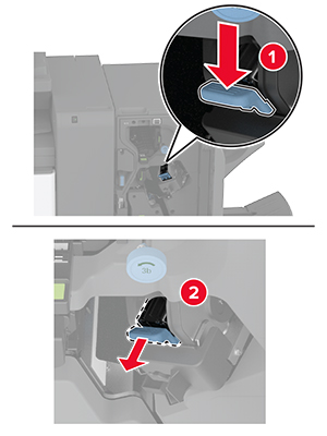
Open the finisher door.
-
Remove the staple cartridge holder.
-
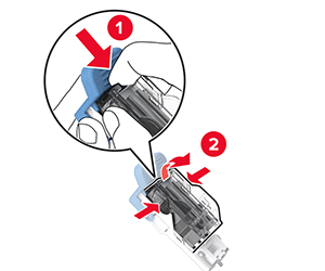
Remove the empty staple cartridge.
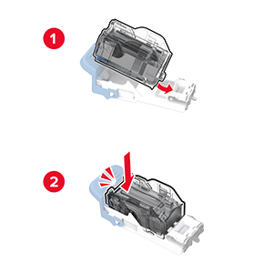
-
Unpack the new staple cartridge.
-
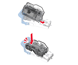
Insert the new staple cartridge into the holder until it
clicks
into place..
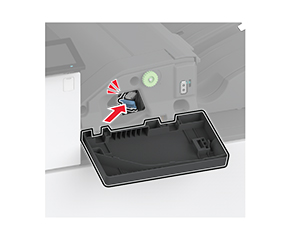
-
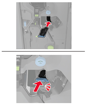
Insert the staple cartridge holder until it
clicks
into place.
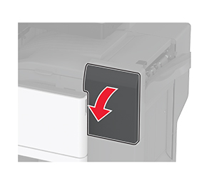
-
Close the door.
Replacing the staple cartridge in the staple, hole punch finisher
-
Open the finisher door.
-
Remove the staple cartridge holder.
-
Remove the empty staple cartridge.
-
Unpack the new staple cartridge.
-
Insert the new staple cartridge until it
clicks
into place.
-
Insert the staple cartridge holder.
-
Close the door.
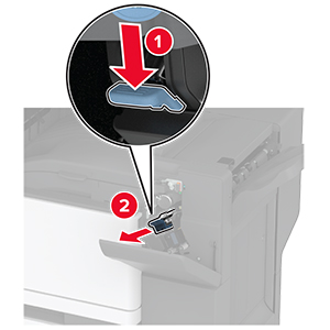
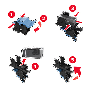
Replacing the standard staple cartridge holder
Replacing the standard staple cartridge holder
-
Open the finisher door.
-
Remove the used staple cartridge holder.
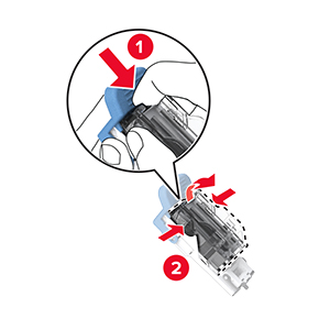
-
Remove the staple cartridge.
-
Unpack the new staple cartridge holder.
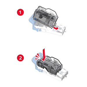
-
Insert the staple cartridge into the new staple cartridge holder until it
clicks
into place.
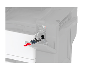
-
Insert the new staple cartridge holder until it
clicks
into place.
-
Close the finisher door.
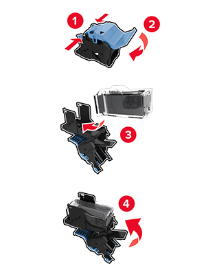
Replacing the staple cartridge holder in the booklet finisher
Replacing the staple cartridge holder in the booklet finisher
-
Open the finisher door, and then pull out the booklet maker.
-
Remove the used staple cartridge holder.
-
Remove the staple cartridge.
-
Unpack the new staple cartridge holder.
-
Insert the staple cartridge into the new staple cartridge holder.
-
Insert the new staple cartridge holder.
-
Insert the booklet maker, and then close the finisher door.
Resetting the supply usage
counters
-
From the home screen, touch
Settings
>
Device
>
Maintenance
>
Configuration Menu
>
Supply Usage And Counters
.
-
Select the counter that you want to reset.
Warning—Potential Damage:
Supplies and parts without Return Program
agreement terms may be reset and remanufactured. However, the manufacturer’s
warranty does not cover any damage caused by non-genuine supplies
or parts. Resetting counters on the supply or part without proper
remanufacturing can cause damage to your printer. After resetting
the supply or part counter, your printer may display an error indicating
the presence of the reset item.
 Note: To avoid spilling the toner, place the unit in an upright position.