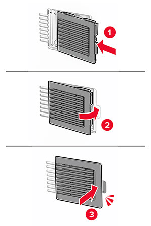
Replacing a toner cartridge
-
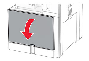
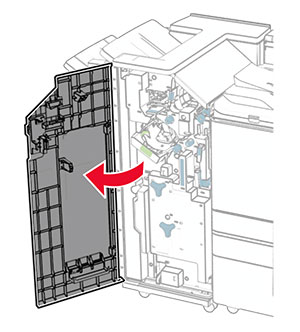
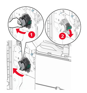
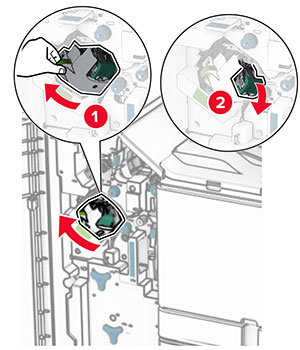
Open the front door.
-
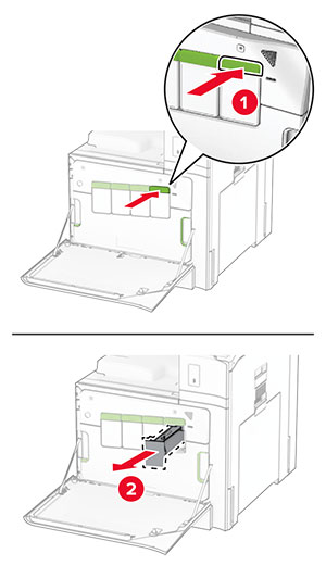
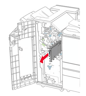
Remove the used toner cartridge.
-
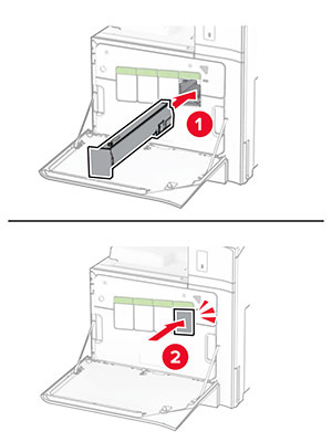
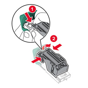
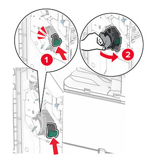
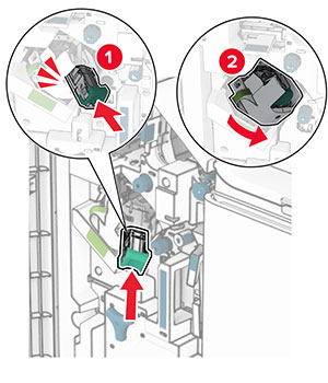
Unpack the new toner cartridge.
-
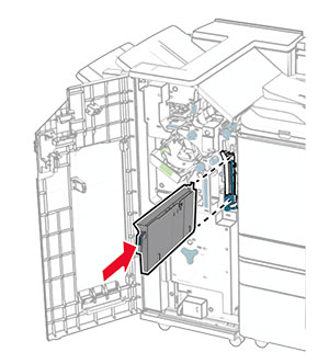
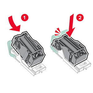
Insert the new toner cartridge until it clicks into place.
-
Close the door.
Open the front door.
Remove the used toner cartridge.
Unpack the new toner cartridge.
Insert the new toner cartridge until it clicks into place.
Close the door.
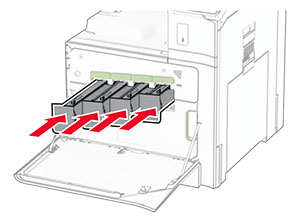
Open the front door.
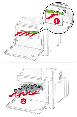
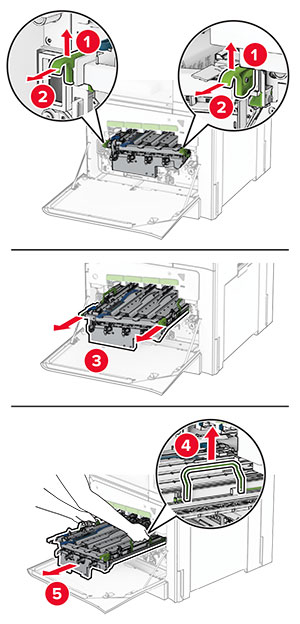
Remove the toner cartridges.
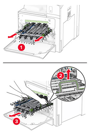
Remove the waste toner bottle.
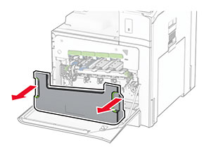
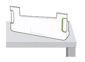
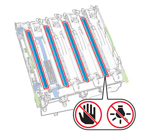
Remove the imaging kit.
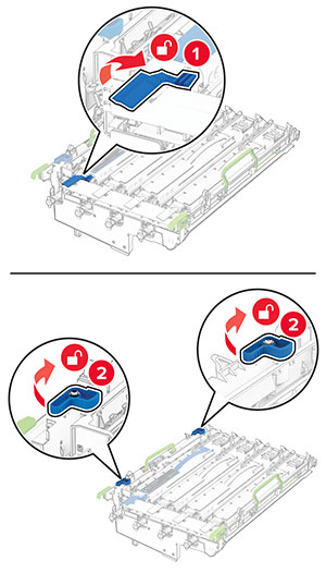
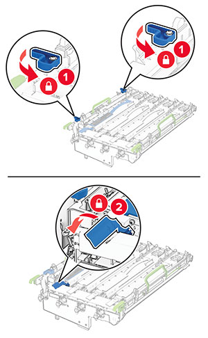
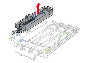
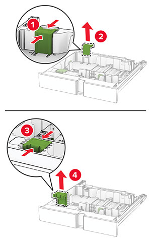
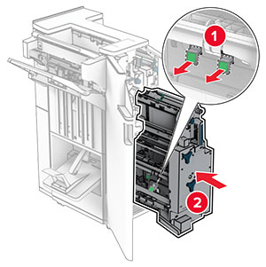
Unlock the used black imaging unit.
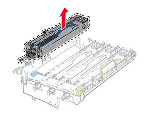
Remove the used black imaging unit.
Unpack the new black imaging unit.
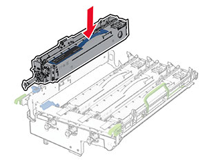
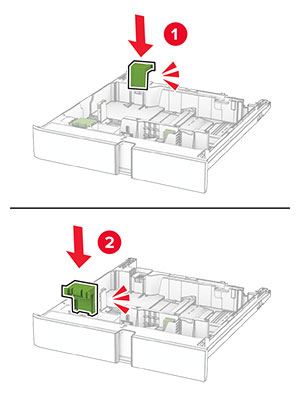
Insert the new black imaging unit.
Lock the new black imaging unit in place.
Insert the imaging kit until it is fully seated.
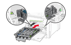
Insert the waste toner bottle until it clicks into place.
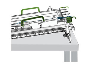
Gently pull out the printhead wipers, and then clean the printhead lenses.
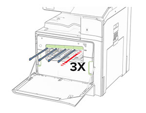
For more information on cleaning the printhead lenses, see Cleaning the printhead lenses .
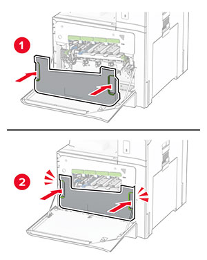
Insert the toner cartridges.
Close the door.
Open the front door.
Remove the toner cartridges.
Remove the waste toner bottle.
Remove the used imaging kit.
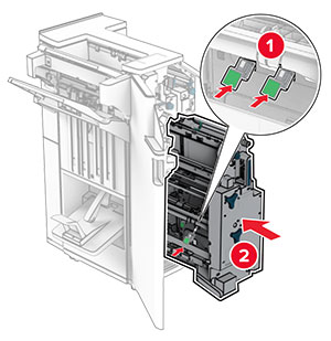
Unlock the black imaging unit.
Remove the black imaging unit.
Unpack the new imaging kit.
Insert the black imaging unit into the new imaging kit.
Lock the black imaging unit in place.
Insert the new imaging kit until it is fully seated.
Insert the waste toner bottle until it clicks into place.
Gently pull out the printhead wipers, and then clean the printhead lenses.
For more information on cleaning the printhead lenses, see Cleaning the printhead lenses .
Insert the toner cartridges.
Close the door.
Open the front door.
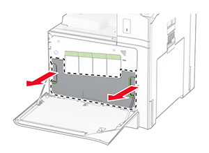
Remove the used waste toner bottle.
Unpack the new waste toner bottle.
Insert the new waste toner bottle until it clicks into place, and then close the door.
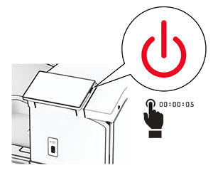
Turn off the printer.
Unplug the power cord from the electrical outlet, and then from the printer.
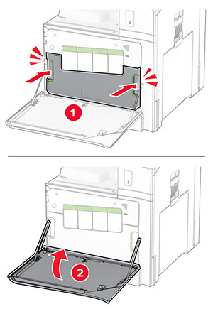
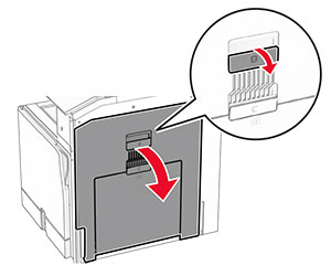
Open door B.
 CAUTION—HOT SURFACE:
The inside of the printer might be hot. To reduce the risk of injury from a hot component, allow the surface to cool before touching it.
CAUTION—HOT SURFACE:
The inside of the printer might be hot. To reduce the risk of injury from a hot component, allow the surface to cool before touching it.
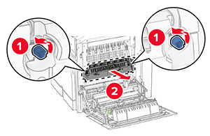
Unlock, and then remove the used fuser.
Unpack the new fuser.
Insert the new fuser until it clicks into place, and then lock it.
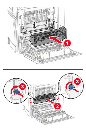
Close door B.
Connect one end of the power cord to the printer, and then the other end to the electrical outlet.
 CAUTION—POTENTIAL INJURY:
To avoid the risk of fire or electrical shock, connect the power cord to an appropriately rated and properly grounded electrical outlet that is near the product and easily accessible.
CAUTION—POTENTIAL INJURY:
To avoid the risk of fire or electrical shock, connect the power cord to an appropriately rated and properly grounded electrical outlet that is near the product and easily accessible.
Turn on the printer.
Pull out the used tray insert.
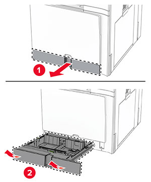
Unpack the new tray insert.
Insert the new tray insert.
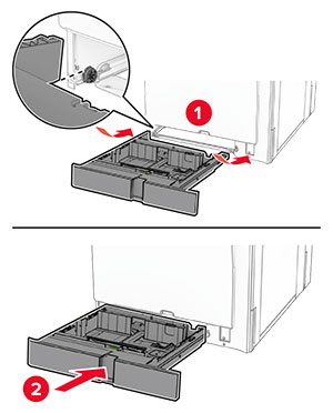
Pull out the tray.
Remove the used size guides.
Unpack the new size guides.
Insert the new size guides until they click into place.
Insert the tray.
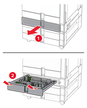
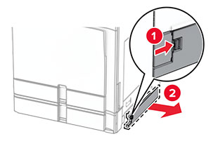
Remove the used tray cover.
Unpack the new tray cover.
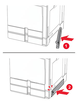
Insert the new tray cover until it clicks into place.
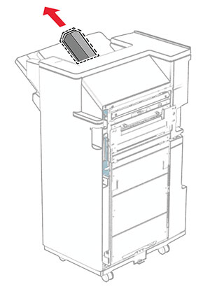
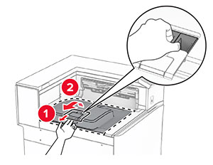
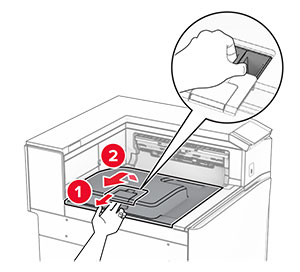
Remove the used top bin extension.
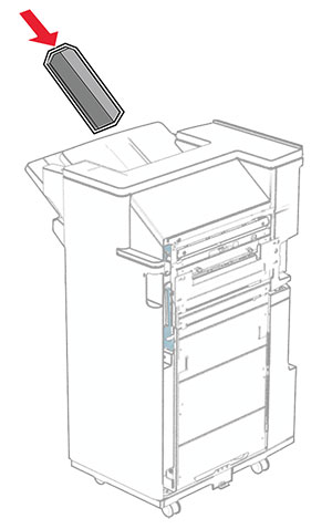
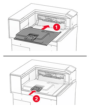
Unpack the new top bin extension.
Insert the new top bin extension.
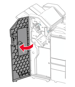
Open the finisher door.
Remove the used hole punch box.
Unpack the new hole punch box.
Insert the new hole punch box.
Close the finisher door.
Remove the used standard bin.
Unpack the new standard bin.
Attach the new standard bin.
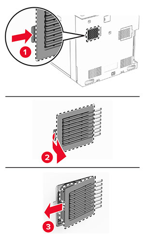
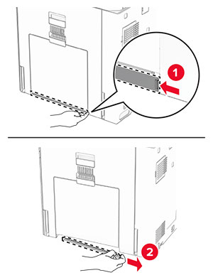
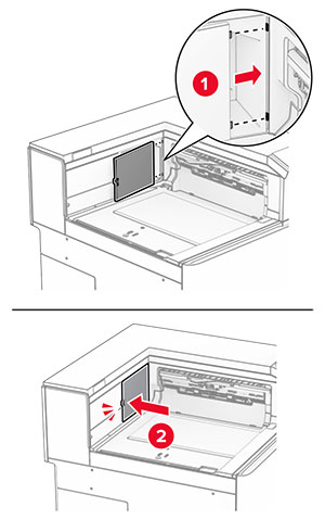
Remove the used fan cover.
Unpack the new cover.
Insert the new cover until it clicks into place.
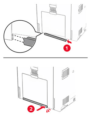
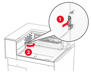
Remove the used right cover.
Unpack the new cover.
Insert the new cover until it clicks into place.
Remove the standard bin.
Remove the used paper transport connector cover.
Unpack the new connector cover.
Attach the new connector cover until it clicks into place.
Attach the standard bin.
Grab handle F, and then slide the staple finisher to the left.
Remove the staple cartridge holder.
Remove the empty staple cartridge.
Insert the new staple cartridge until it clicks into place.
Insert the staple cartridge holder until it clicks into place.
Slide the staple finisher to the right.
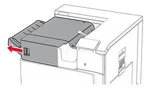
Open door H.
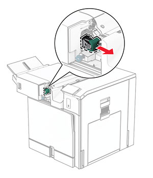
Pull out the green handle, and then remove the staple cartridge holder.
Remove the empty staple cartridge.
Unpack the new staple cartridge.
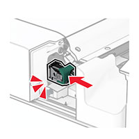
Insert the new staple cartridge until it clicks into place.
Insert the staple cartridge holder until it clicks into place.
Close door H.
Open door H.
Pull out the green handle, and then remove the staple cartridge holder.
Remove the empty staple cartridge.
Unpack the new staple cartridge.
Insert the new staple cartridge until it clicks into place.
Insert the staple cartridge holder until it clicks into place.
Close door H.
Open the finisher door.
Pull out the booklet maker, and then remove the used staple cartridge holders.
Unpack the new staple cartridge holders.
Insert the new staple cartridge holders.
Insert the booklet maker, and then close the finisher door.
From the control panel, navigate to Settings > Device > Maintenance > Configuration Menu > Supply Usage And Counters .
Select the counter that you want to reset.