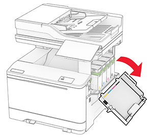
Replacing a toner cartridge
-
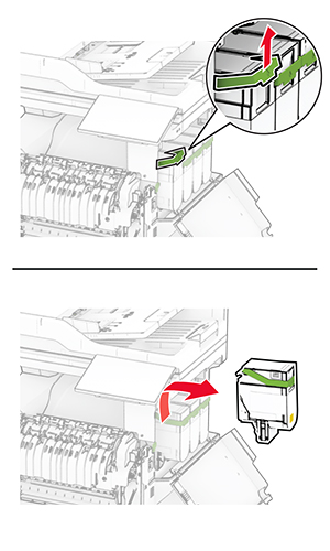
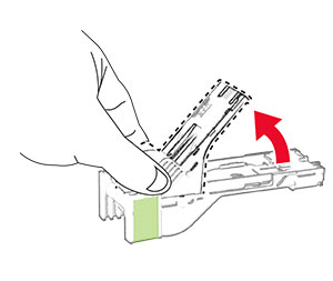
Open door B.
-
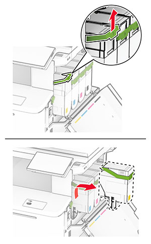
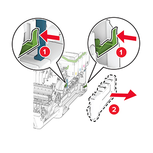
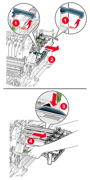
Remove the used toner cartridge.
-
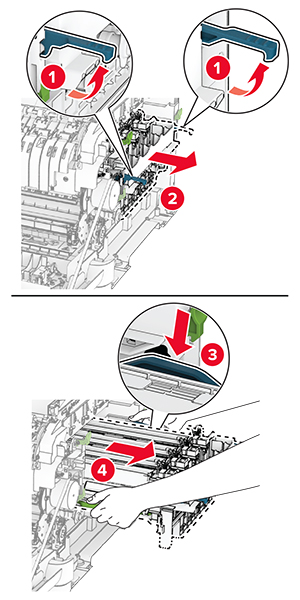
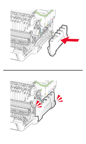
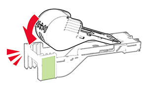
Unpack the new toner cartridge.
-
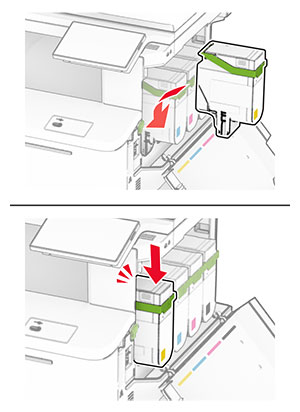
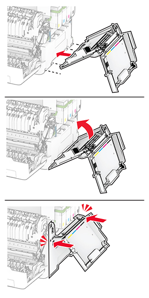
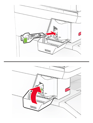
Insert the new toner cartridge until it clicks into place.
-
Close the door.
Open door B.
Remove the used toner cartridge.
Unpack the new toner cartridge.
Insert the new toner cartridge until it clicks into place.
Close the door.
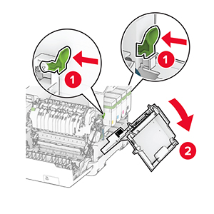
Open door B.
Open door A.
 CAUTION—HOT SURFACE:
The inside of the printer might be hot. To reduce the risk of injury from a hot component, allow the surface to cool before touching it.
CAUTION—HOT SURFACE:
The inside of the printer might be hot. To reduce the risk of injury from a hot component, allow the surface to cool before touching it.

Remove the right cover.
Remove the waste toner bottle.

Remove the toner cartridges.
Remove the used imaging kit.
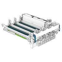
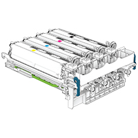
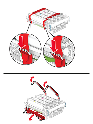
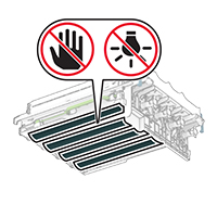
Unpack the new imaging kit.
|
Black imaging kit |
Black and color imaging kit |
|---|---|
|
|
Notes:
Remove the packing material.
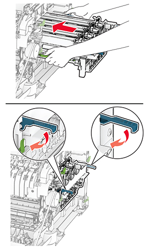
Insert the new imaging kit until it is fully seated.
Insert the toner cartridges until they click into place.
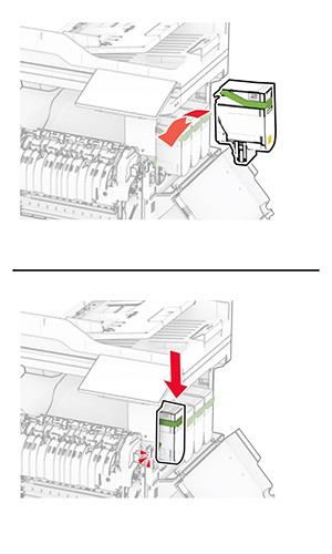
Insert the waste toner bottle until it clicks into place.
Attach the right cover until it clicks into place.
Close door A, and then close door B.
Open door B.
Open door A.
CAUTION—HOT SURFACE:
The inside of the printer might be hot. To reduce the risk of injury from a hot component, allow the surface to cool before touching it.
Remove the right cover.
Remove the used waste toner bottle.
Unpack the new waste toner bottle.
Insert the new waste toner bottle until it clicks into place.
Attach the right cover until it clicks into place.
Close door A, and then close door B.
Open door B.
Open door A.
CAUTION—HOT SURFACE:
The inside of the printer might be hot. To reduce the risk of injury from a hot component, allow the surface to cool before touching it.
Remove the right cover.
Remove the waste toner bottle.
Remove the toner cartridges.
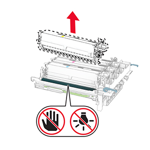
Remove the imaging kit.
Remove the used developer unit.
Remove the packing material.
Insert the new developer unit.
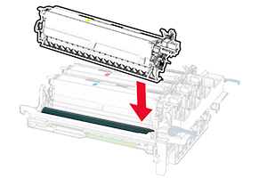
Insert the imaging kit until it is fully seated.
Insert the toner cartridges until they click into place.
Insert the waste toner bottle until it clicks into place.
Attach the right cover until it clicks into place.
Close door A, and then close door B.
Turn off the printer.
Unplug the power cord from the electrical outlet, and then from the printer.
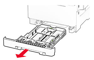
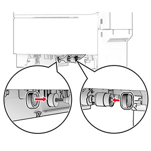
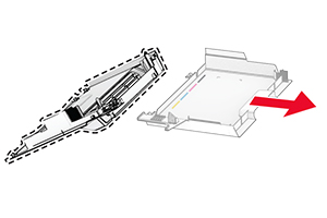
Remove the tray.
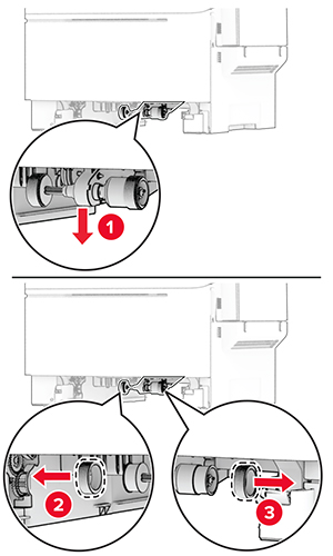
Remove the used pick tires.
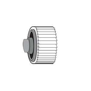
Unpack the new pick tires.
Insert the new pick tires.
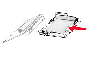
Insert the tray.
Connect the power cord to the printer, and then to the electrical outlet.
 CAUTION—POTENTIAL INJURY:
To avoid the risk of fire or electrical shock, connect the power cord to an appropriately rated and properly grounded electrical outlet that is near the product and easily accessible.
CAUTION—POTENTIAL INJURY:
To avoid the risk of fire or electrical shock, connect the power cord to an appropriately rated and properly grounded electrical outlet that is near the product and easily accessible.
Turn on the printer.
Open door B.
Open door A.
CAUTION—HOT SURFACE:
The inside of the printer might be hot. To reduce the risk of injury from a hot component, allow the surface to cool before touching it.
Remove the used right cover.
Remove door B from the used right cover.
Unpack the new right cover.
Attach door B to the new right cover.
Attach the new right cover until it clicks into place.
Close door A, and then close door B.
 CAUTION—SHOCK HAZARD:
To avoid the risk of electrical shock, if you are accessing the controller board or installing optional hardware or memory devices sometime after setting up the printer, then turn the printer off, and unplug the power cord from the electrical outlet before continuing. If you have any other devices attached to the printer, then turn them off as well, and unplug any cables going into the printer.
CAUTION—SHOCK HAZARD:
To avoid the risk of electrical shock, if you are accessing the controller board or installing optional hardware or memory devices sometime after setting up the printer, then turn the printer off, and unplug the power cord from the electrical outlet before continuing. If you have any other devices attached to the printer, then turn them off as well, and unplug any cables going into the printer.
Turn off the printer.
Unplug the power cord from the electrical outlet, and then from the printer.
Using a flat-head screwdriver, remove the controller board shield.
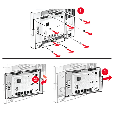
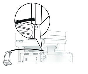
Open door B.
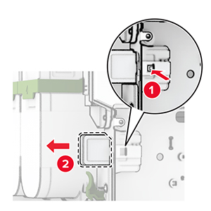
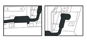
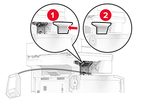
Remove the used wireless print server.
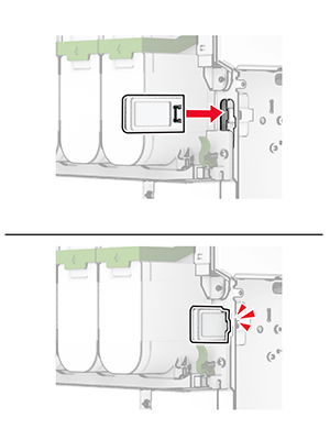
Unpack the new wireless print server.
Insert the new wireless print server until it clicks into place.
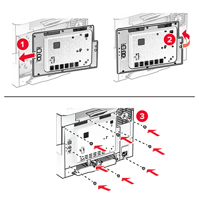
Close door B.
Attach the controller board shield, and then install the screws.
Connect the power cord to the printer, and then to the electrical outlet.
CAUTION—POTENTIAL INJURY:
To avoid the risk of fire or electrical shock, connect the power cord to an appropriately rated and properly grounded electrical outlet that is near the product and easily accessible.
Turn on the printer.
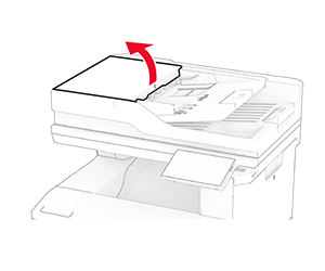
Open door C.
Remove the used ADF pick roller.
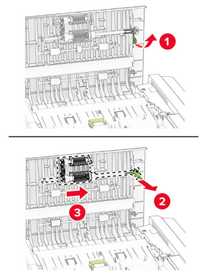
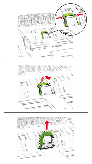
Remove the used ADF separator roller.
Unpack the new ADF pick roller and ADF separator roller.
Insert the new ADF separator roller until it clicks into place.
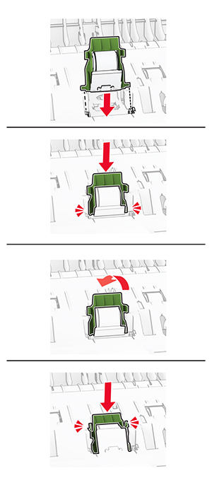
Insert the new ADF pick roller until it clicks into place.
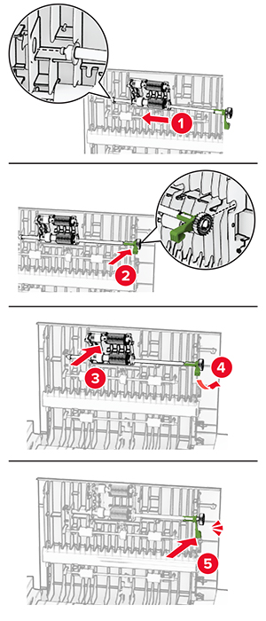
Close door C.
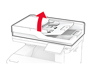
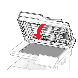
Open the scanner cover.
Remove the used scanner glass pad.
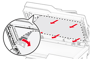
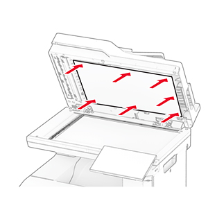
Unpack the new scanner glass pad.
Align the new scanner glass pad to the scanner glass.
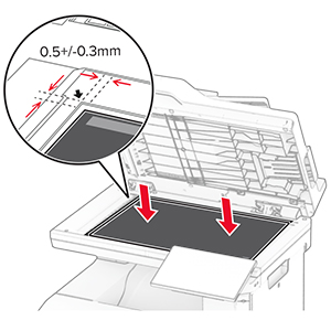
Close the scanner cover to attach the new scanner glass pad.
Open the scanner cover.
Apply pressure to the scanner glass pad to secure it.
Close the scanner cover.
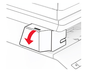
Open the convenience stapler access door.
Remove the staple cartridge.
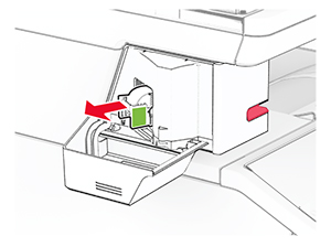
Remove the empty staple refill.
Insert the new staple refill until it clicks into place.
Insert the staple cartridge, and then close the convenience stapler access door.
Turn off the printer.
Unplug the power cord from the electrical outlet, and then from the printer.
Unplug the power supply from the electrical outlet.
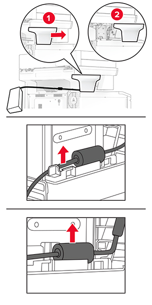
Remove the column cover and power supply cable.
Remove the convenience stapler.
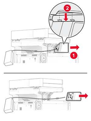
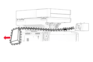
Remove the used power supply.
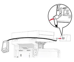
Unpack the new power supply.
Insert the new power supply through the printer, and then connect it to the convenience stapler.
Install the convenience stapler.
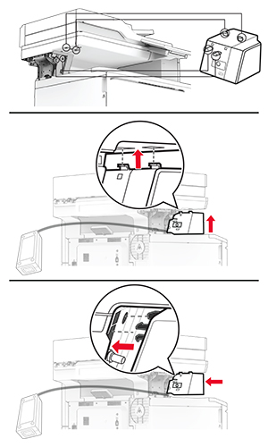
Position the power supply properly.
Attach the column cover.
Connect one end of the stapler power cord to the power supply, and then the other end to the electrical outlet.
Connect one end of the printer power cord to the printer, and then the other end to the electrical outlet.
CAUTION—POTENTIAL INJURY:
To avoid the risk of fire or electrical shock, connect the power cord to an appropriately rated and properly grounded electrical outlet that is near the product and easily accessible.
Turn on the printer.
From the home screen, touch Settings > Device > Maintenance > Configuration Menu > Supply Usage And Counters .
Select the counter that you want to reset.