Installing optional trays
 CAUTION—SHOCK HAZARD:
To avoid the risk of electrical shock, if you are accessing the controller board or installing optional hardware or memory devices sometime after setting up the printer, then turn the printer off, and unplug the power cord from the electrical outlet before continuing. If you have any other devices attached to the printer, then turn them off as well, and unplug any cables going into the printer.
CAUTION—SHOCK HAZARD:
To avoid the risk of electrical shock, if you are accessing the controller board or installing optional hardware or memory devices sometime after setting up the printer, then turn the printer off, and unplug the power cord from the electrical outlet before continuing. If you have any other devices attached to the printer, then turn them off as well, and unplug any cables going into the printer.
-
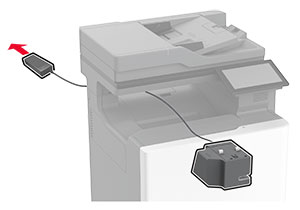
Turn off the printer.
-
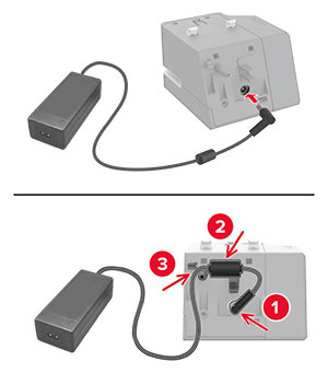
Unplug the power cord from the electrical outlet, and then from the printer.
-
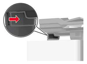
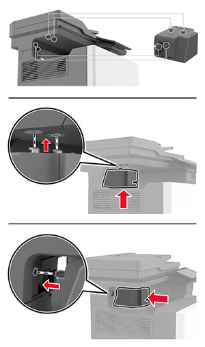
Unpack the optional tray, and then remove all the packing material.
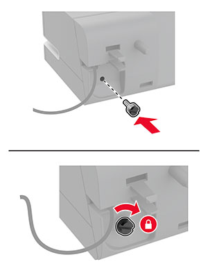
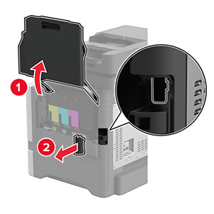
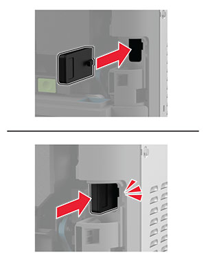
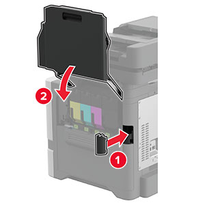
Note: If optional trays are already installed, then unlock them from the printer before lifting the printer. Do not try to lift the printer and trays at the same time. -
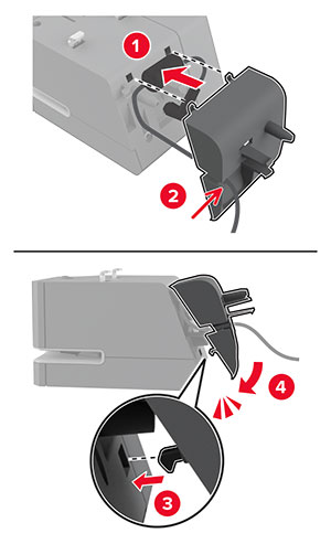
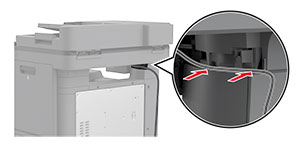
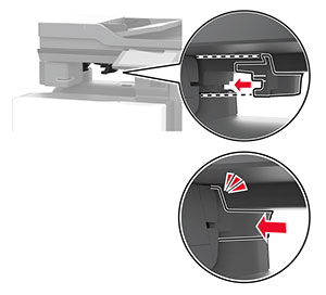
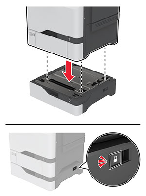
Install the printer on top of the optional tray until it clicks into place.
 CAUTION—POTENTIAL INJURY:
If the printer weight is greater than 20 kg (44 lb), then it may require two or more people to lift it safely.
CAUTION—POTENTIAL INJURY:
If the printer weight is greater than 20 kg (44 lb), then it may require two or more people to lift it safely.
-
Connect the power cord to the printer, and then to the electrical outlet.
CAUTION—POTENTIAL INJURY:
To avoid the risk of fire or electrical shock, connect the power cord to an appropriately rated and properly grounded electrical outlet that is near the product and easily accessible.
-
Turn on the printer.
Add the tray in the print driver to make it available for print jobs. For more information, see Adding available options in the print driver .