CAUTION—TIPPING HAZARD:
Installing one or more options on your printer or MFP may require a caster base, furniture, or other feature to prevent instability causing possible injury. For more information on supported configurations, see
www.lexmark.com/multifunctionprinters
.
-
From the control panel, press and hold the power button for 5 seconds to turn off the printer.
-
Unplug the power cord from the electrical outlet, and then from the printer.
-
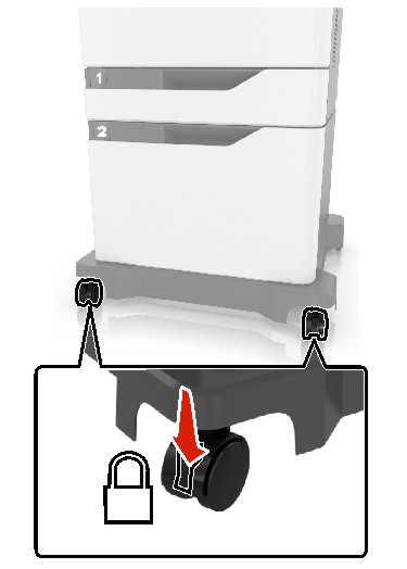
Lock the caster base wheels to keep the printer from moving.
-
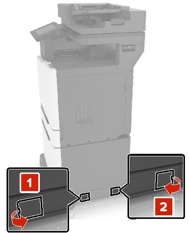
Open the covers at the side of the caster base.
-
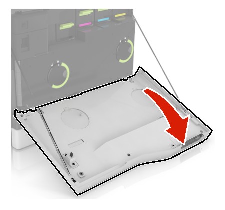
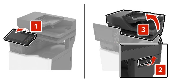
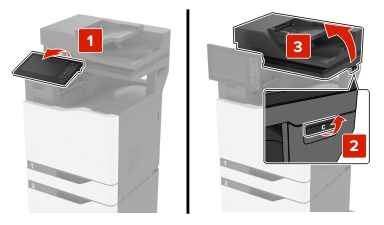
Open door C.
-
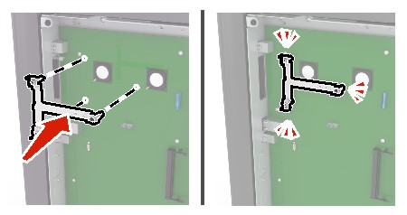
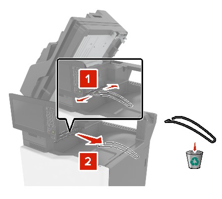
Remove the paper bail.
-
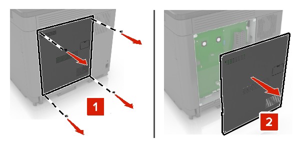
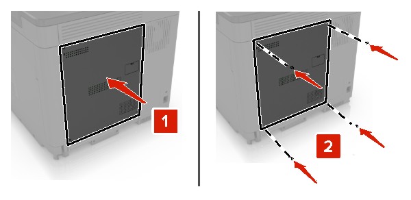
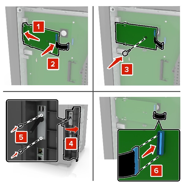
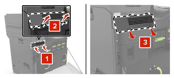
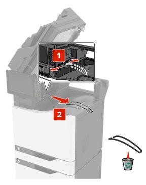
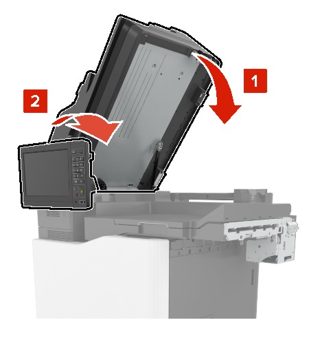
Remove the covers.
-
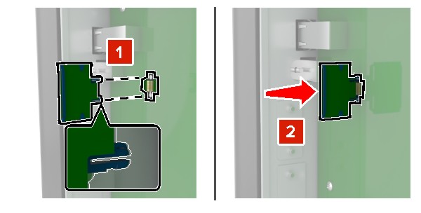
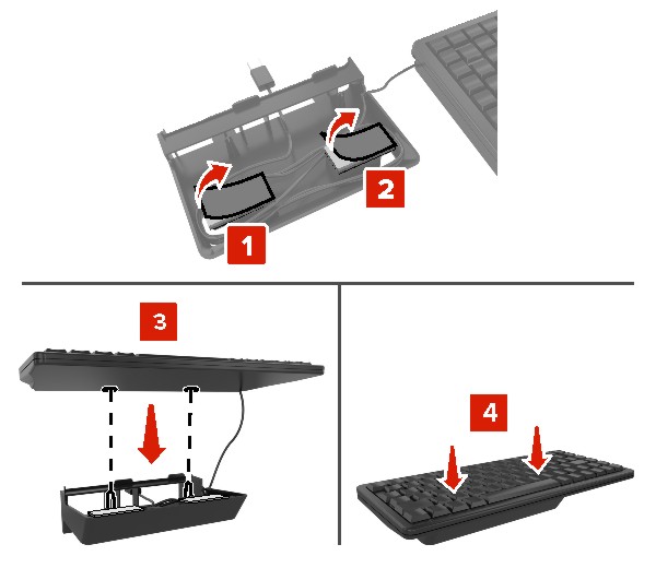
Unpack the paper transport, and then remove the pieces of tape.
-
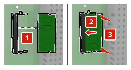
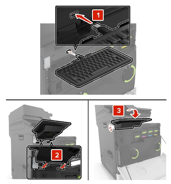
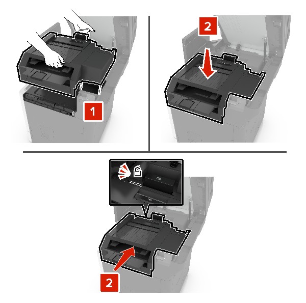
Lift, and then align the paper transport to the printer.
-
Firmly push the paper transport until it
clicks
into place.
-
Close door C.
 CAUTION—PINCH HAZARD:
To avoid the risk of a pinch injury, keep hands clear of the labeled area when closing door C.
-
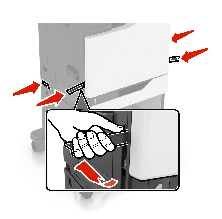
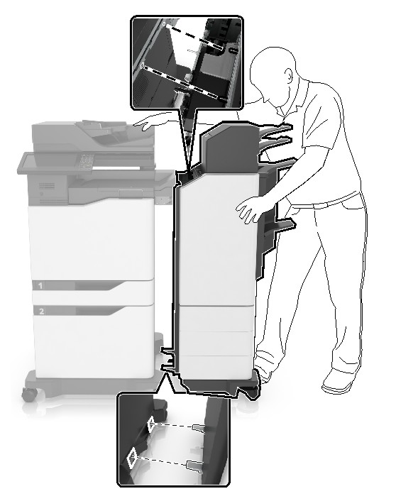
Unpack the multiposition staple, hole punch finisher, and then remove the pieces of tape.
-
On a flat, sturdy, and stable surface, align the finisher to the printer.
Note:
Avoid installing the finisher on a carpeted surface.
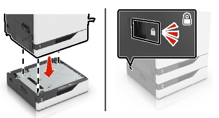
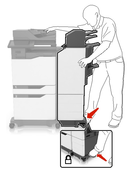
-
Push the finisher to the printer by applying pressure at the bottom of the finisher until it
clicks
into place.
Check if the finisher and printer are properly locked by pulling hard the finisher away from the printer. If the finisher detaches from the printer, then repeat
step 13
through
step 14
until they are properly locked.
-
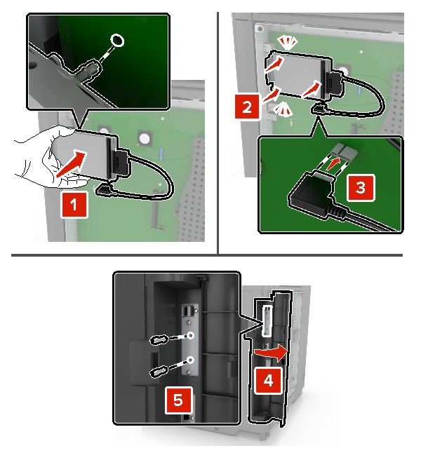
When the finisher is locked, do the following:
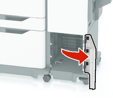
-
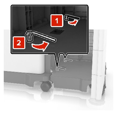
Open the bottom front door of the finisher.
-
Turn the levers of the finisher counterclockwise until the levers are loose.
-
Close the door.
-
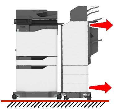
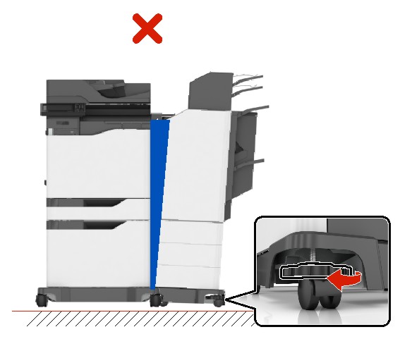
Check the gap between the printer and the finisher.
If the gap is uneven, then do either of the following:
-
To fix the gap at the top, rotate the side wheels of the finisher clockwise.
-
To fix the gap at the bottom, rotate the side wheels of the finisher counterclockwise.
-
Connect the power cords to the finisher and the printer, and then connect them to a properly grounded electrical outlet.
 CAUTION—POTENTIAL INJURY:
To avoid the risk of fire or electrical shock, connect the power cord to an appropriately rated and properly grounded electrical outlet that is near the product and easily accessible.
CAUTION—POTENTIAL INJURY:
Do not use this product with extension cords, multioutlet power strips, multioutlet extenders, or UPS devices. The power capacity of these types of accessories can be easily overloaded by a laser printer and may result in a risk of fire, property damage, or poor printer performance.
-
Turn on the printer.
If necessary, manually add the finisher in the print driver to make it available for print jobs.
CAUTION—PINCH HAZARD:
To avoid the risk of a pinch injury, keep hands clear of the labeled area during print jobs that use the stapler in the multiposition staple, hole punch finisher.
 CAUTION—SHOCK HAZARD:
To avoid the risk of electrical shock, if you are accessing the controller board or installing optional hardware or memory devices sometime after setting up the printer, then turn the printer off, and unplug the power cord from the electrical outlet before continuing. If you have any other devices attached to the printer, then turn them off as well, and unplug any cables going into the printer.
CAUTION—SHOCK HAZARD:
To avoid the risk of electrical shock, if you are accessing the controller board or installing optional hardware or memory devices sometime after setting up the printer, then turn the printer off, and unplug the power cord from the electrical outlet before continuing. If you have any other devices attached to the printer, then turn them off as well, and unplug any cables going into the printer.