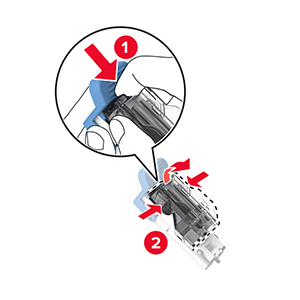
Replacing a toner cartridge
-
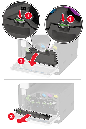
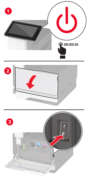
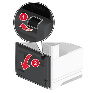
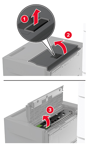
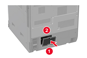
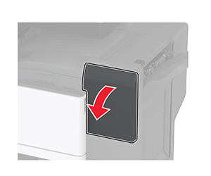
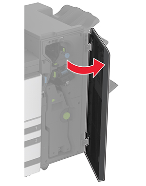
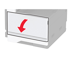
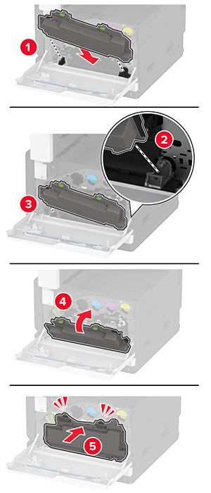
Open the front door.
-
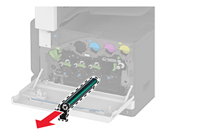
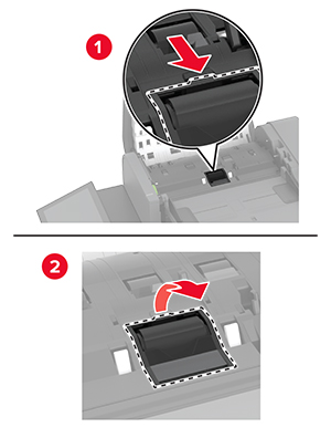
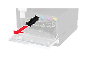
Remove the used toner cartridge.
-
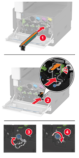
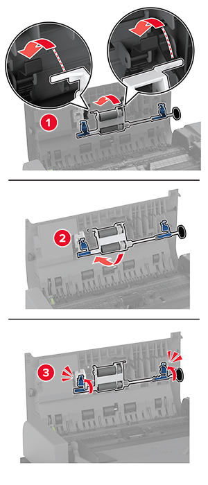
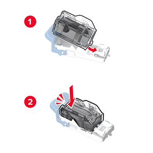
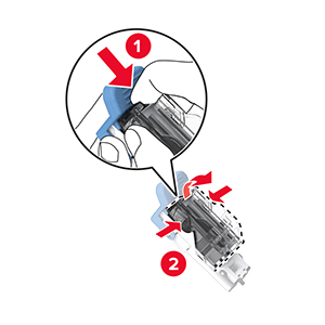
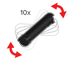
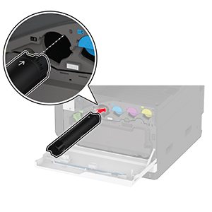
Unpack the new toner cartridge.
-
Shake the toner cartridge to redistribute the toner.
-
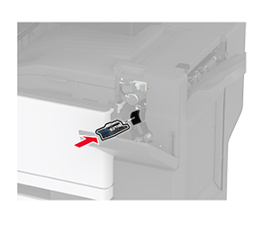
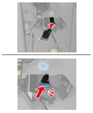
Insert the new toner cartridge.
-
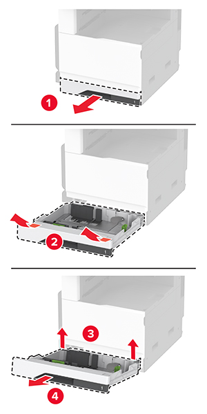
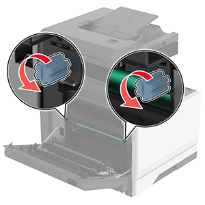
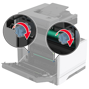
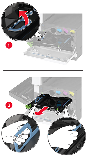
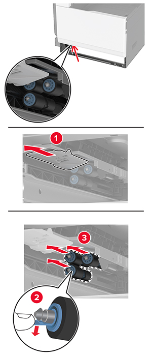
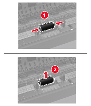
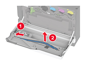
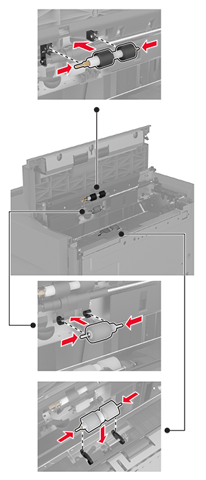
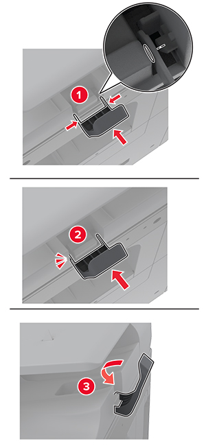
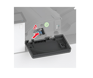
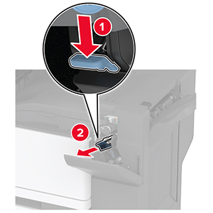
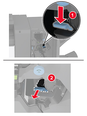
Unlock the waste toner bottle.

-
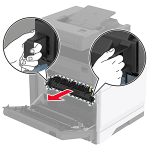
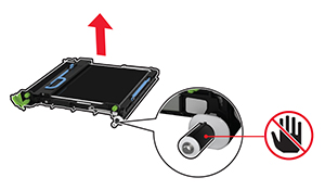
Remove the waste toner bottle.
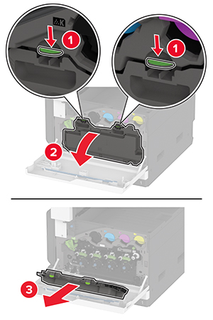 Note: To avoid spilling the toner, place the bottle in an upright position.
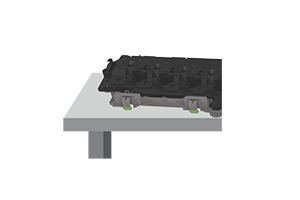
-
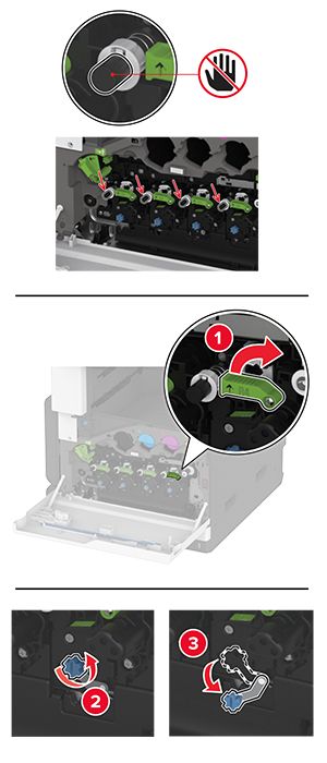
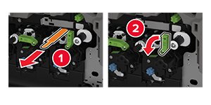
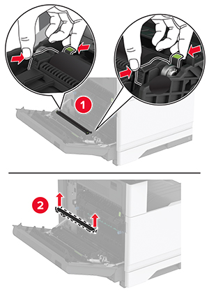
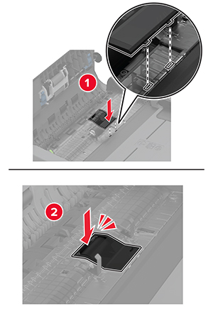
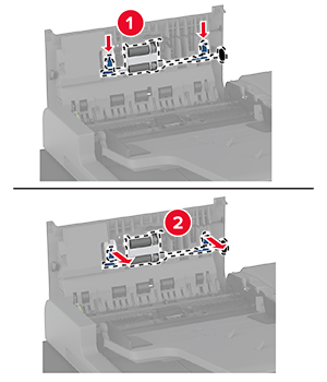
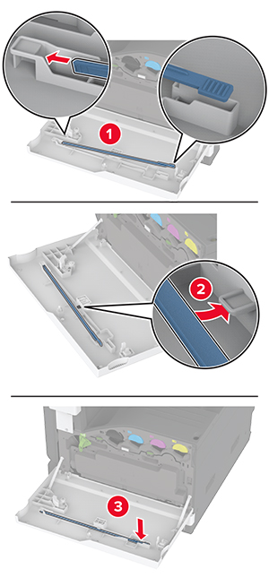
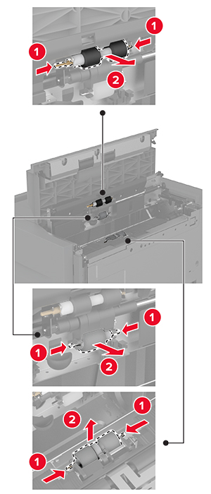
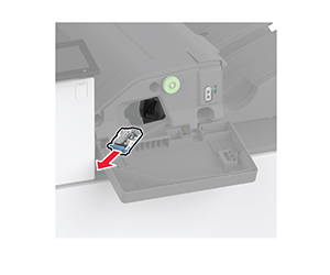
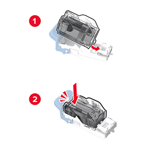
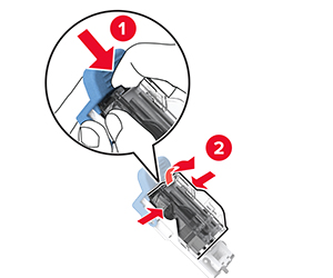
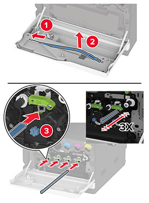
Remove the printhead wiper, and then clean the printhead lenses.
-
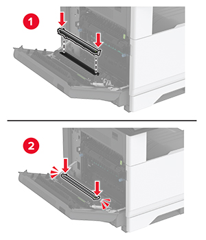
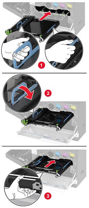
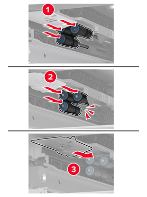
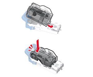
Insert the printhead wiper back into place.
-
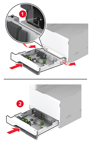
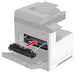
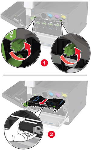
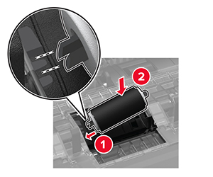
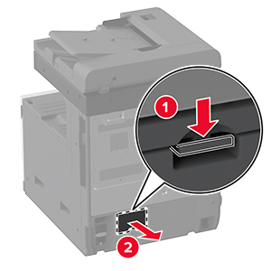
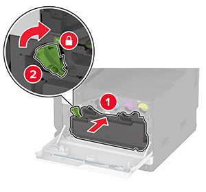
Insert the waste toner bottle until it clicks into place.
-
Lock the waste toner bottle.
-
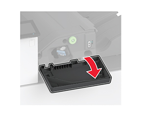
Close the door.