Printer configurations
 CAUTION—POTENTIAL INJURY: To reduce the risk of equipment instability, load each tray separately. Keep all other trays closed until needed.
MS510dn and MS517dn
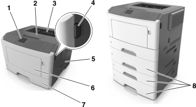
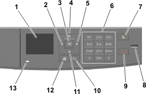
1 | Control panel |
2 | Paper stop |
3 | Standard bin |
4 | Front door release button |
5 | Controller board access door |
6 | 100-sheet multipurpose feeder |
7 | Standard 250-sheet tray |
8 | Optional 250- or 550-sheet trays |
MS610dn and MS617dn

1 | Printer control panel |
2 | Paper stop |
3 | Standard bin |
4 | Front door release button |
5 | Controller board access door |
6 | 100-sheet multipurpose feeder |
7 | Standard 550-sheet tray |
8 | Optional 250- or 550-sheet trays |