CAUTION—SHOCK HAZARD:
To avoid the risk of electrical shock, if you are accessing the controller board or installing optional hardware or memory devices sometime after setting up the printer, then turn the printer off, and unplug the power cord from the electrical outlet before continuing. If you have any other devices attached to the printer, then turn them off as well, and unplug any cables going into the printer.
-
Turn off the printer.
-
Unplug the power cord from the electrical outlet, and then from the printer.
-
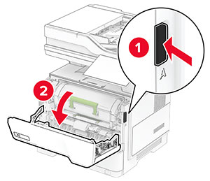
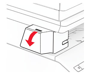
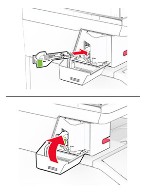
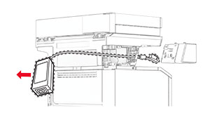
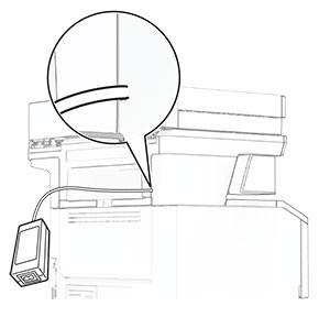
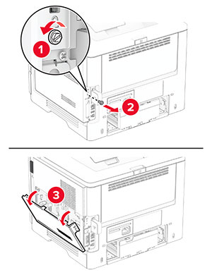
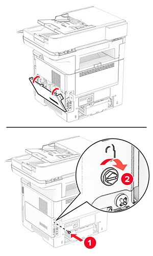
Open the controller board access cover.
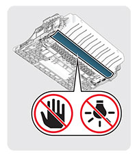
Warning—Potential Damage:
Controller board electronic components are easily damaged by static electricity. Touch a metal surface on the printer before touching any controller board components or connectors.
-
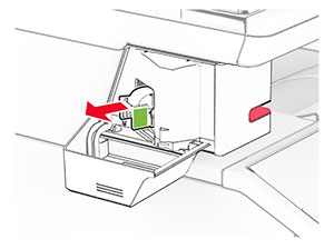
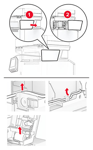
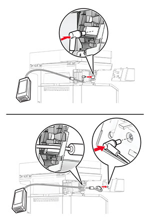
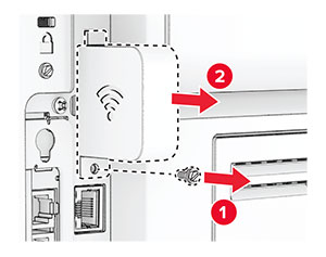
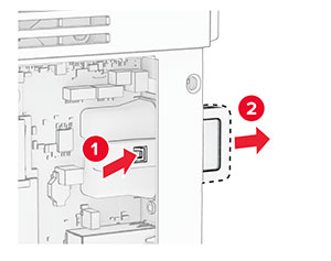
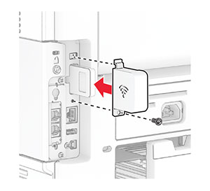
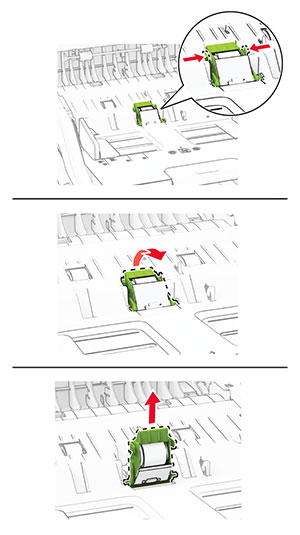
Remove the wireless print server cover.
-
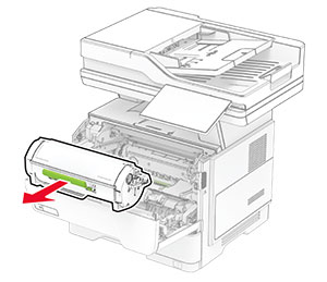
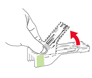
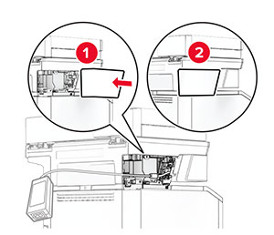
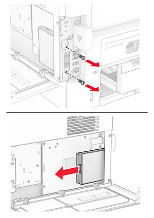
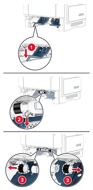
Remove the fax card.
-
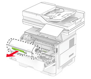
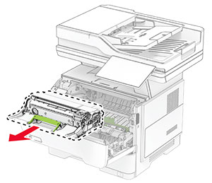
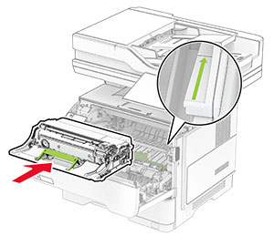
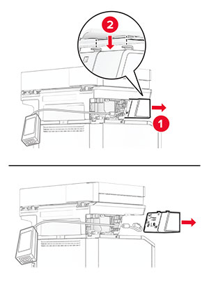
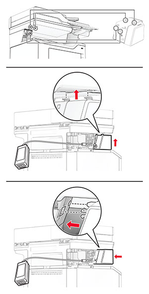
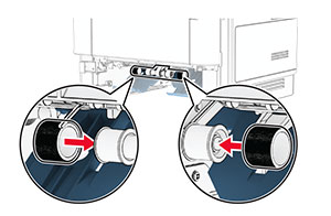
Remove the used wireless print server.
-
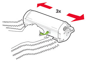
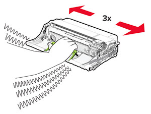
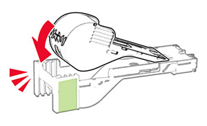
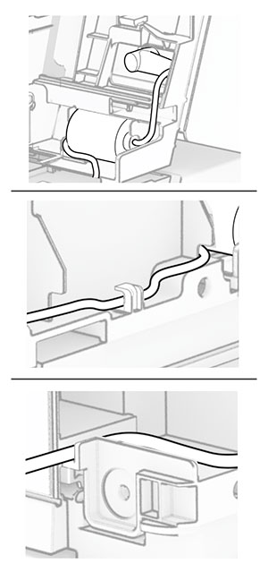
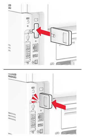
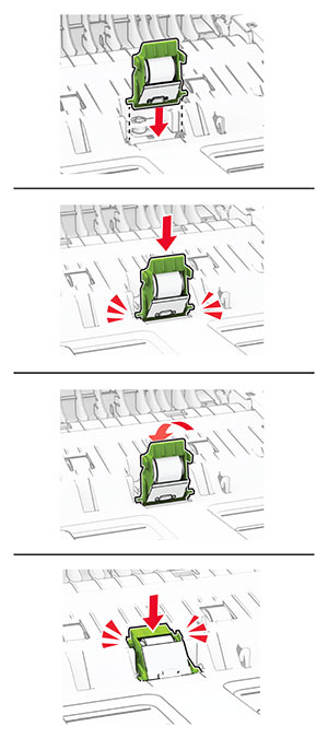
Unpack the new wireless print server.
-
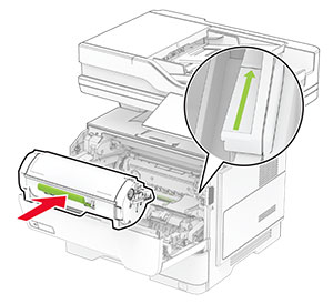
Insert the new wireless print server until it
clicks
into place.
-
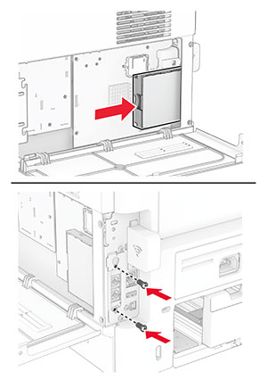
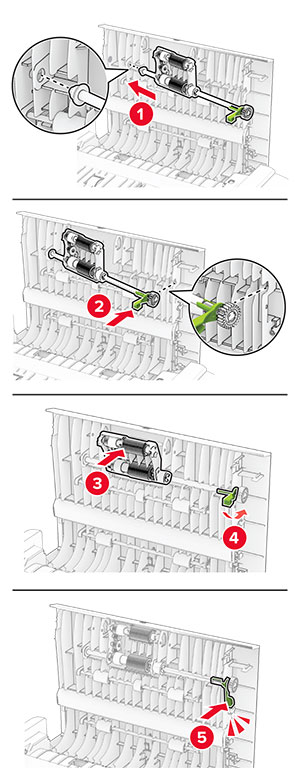
Insert the fax card, and then install the screws.
-
Attach the wireless print server cover, and then install the screw.
-
Close the controller board access cover, and then install the screw.
-
Connect the power cord to the printer, and then to the electrical outlet.
 CAUTION—POTENTIAL INJURY:
To avoid the risk of fire or electrical shock, connect the power cord to an appropriately rated and properly grounded electrical outlet that is near the product and easily accessible.
-
Turn on the printer.