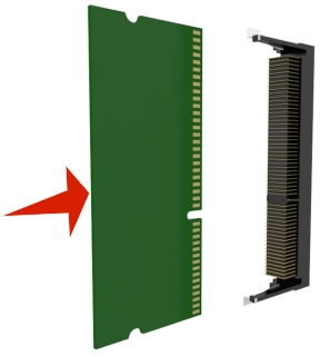
The controller board supports one optional Lexmark Internal Solutions Port (ISP).
 CAUTION—SHOCK HAZARD:
 If you are accessing the controller board or installing optional hardware or memory devices sometime after setting up the printer, then turn the printer off, and unplug the power cord from the electrical outlet before continuing. If you have any other devices attached to the printer, then turn them off as well, and unplug any cables going into the printer.
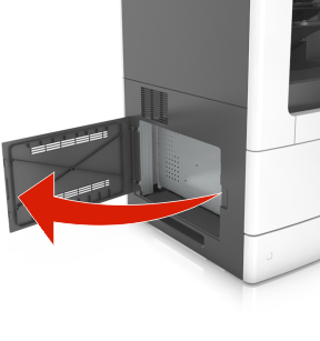
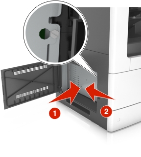
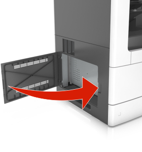
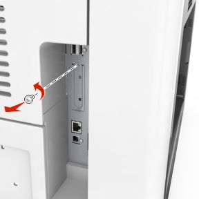
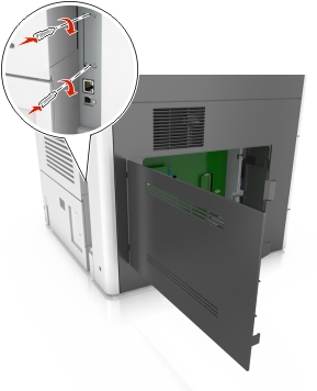
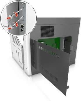
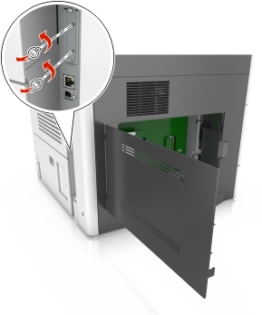
Access the controller board.
For more information, see Accessing the controller board.
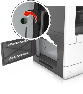
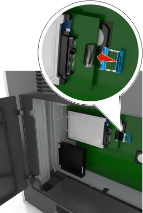
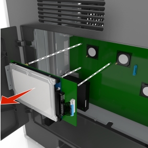
If a printer hard disk is installed, then remove the printer hard disk first.
For more information, see Removing a printer hard disk.
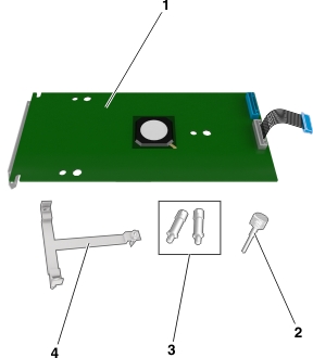
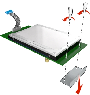
Unpack the ISP kit.
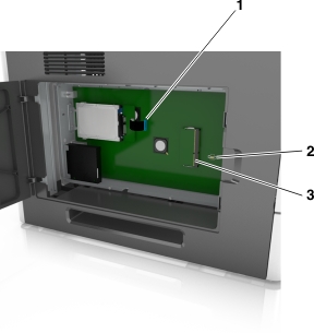
1 | ISP solution |
2 | Screw for attaching the plastic bracket to the ISP |
3 | Screws for attaching the ISP mounting bracket to the controller board shield |
4 | Plastic bracket |
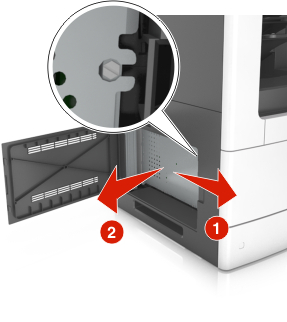
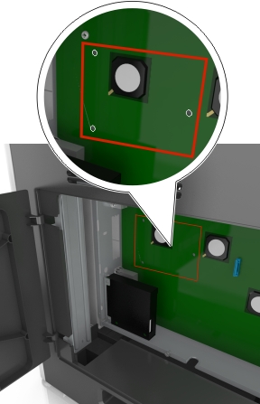
Remove the metal cover from the ISP opening.
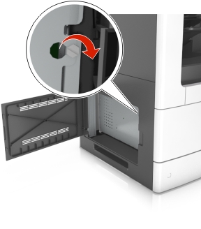
Loosen the screw.
Lift the metal cover, and then pull it out completely.
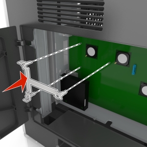
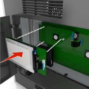
Align the posts of the plastic bracket to the holes on the controller board cage, and then press the plastic bracket on the controller board cage until it clicks into place.
Note: Make sure that the plastic bracket has latched completely, and that the plastic bracket is seated firmly on the cage.
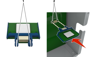
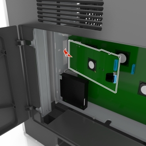
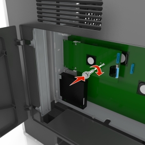
Install the ISP on the plastic bracket.
Note: Hold the ISP at an angle over the plastic bracket so that any overhanging connectors will pass through the ISP opening in the cage.
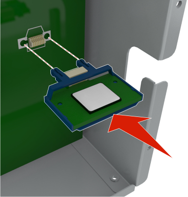
Lower the ISP toward the plastic bracket until the ISP is seated between the guides of the plastic bracket.
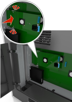
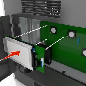
Use the provided thumbscrew for the ISP to attach the plastic bracket to the ISP.
Note: Turn the screw clockwise, enough to hold the ISP in place, but do not tighten it yet.
Attach the two provided screws to secure the ISP mounting bracket to the controller board shield.
Tighten the thumbscrew that is attached to the ISP.
Warning—Potential Damage: Do not screw it on too tightly.
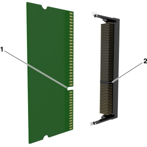
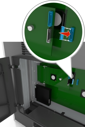
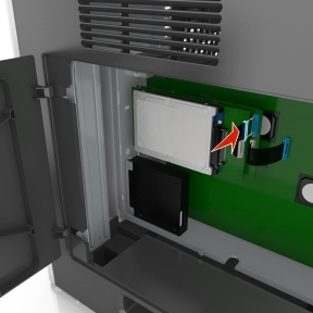
Connect the ISP solution interface cable into the receptacle of the controller board.
Note: The plugs and receptacles are color-coded.