
| | CAUTION—SHOCK HAZARD: If you are accessing the controller board or installing optional hardware or memory devices sometime after setting up the printer, then turn the printer off, and unplug the power cord from the electrical outlet before continuing. If you have any other devices attached to the printer, then turn them off as well, and unplug any cables going into the printer. |
| Warning—Potential Damage: Controller board electronic components are easily damaged by static electricity. Touch a metal surface on the printer before touching any controller board electronic components or connectors. |
Memory card
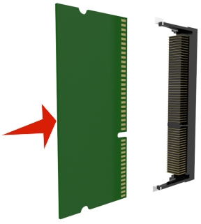
DDR3 DIMM
Flash memory
Fonts
Firmware cards
Forms Barcode
Prescribe
IPDS
Printcryption
Printer hard disk
LexmarkTM Internal Solutions Ports (ISP)
Parallel 1284-B interface
MarkNetTM N8350 802.11 b/g/n wireless printer server
MarkNet N8130 10/100 fiber interface
RS-232-C serial interface
| | CAUTION—SHOCK HAZARD: If you are accessing the controller board or installing optional hardware or memory devices sometime after setting up the printer, then turn the printer off, and unplug the power cord from the electrical outlet before continuing. If you have any other devices attached to the printer, then turn them off as well, and unplug any cables going into the printer. |
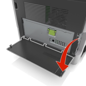
Open the controller board access door.
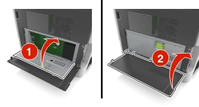
Open the controller board shield using the green handle.

Use the following illustration to locate the appropriate connector.
| Warning—Potential Damage: Controller board electronic components are easily damaged by static electricity. Touch something metal on the printer before touching any controller board electronic components or connectors. |
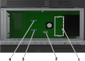
1 | Memory card connector |
2 | Option card connector |
3 | Printer hard disk connector |
4 | Lexmark Internal Solutions Port connector |
Close the shield, and then the access door.
| | CAUTION—SHOCK HAZARD: If you are accessing the controller board or installing optional hardware or memory devices sometime after setting up the printer, then turn the printer off, and unplug the power cord from the electrical outlet before continuing. If you have any other devices attached to the printer, then turn them off as well, and unplug any cables going into the printer. |
| Warning—Potential Damage: Controller board electronic components are easily damaged by static electricity. Touch something metal on the printer before touching any controller board electronic components or connectors. |
| Note: An optional memory card can be purchased separately and attached to the controller board. |
Access the controller board.
For more information, see Accessing the controller board.
Unpack the memory card.
| Warning—Potential Damage: Do not touch the connection points along the edge of the card. Doing so may cause damage. |
Align the notch (1) on the memory card with the ridge (2) on the connector.
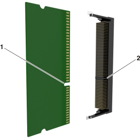
Push the memory card straight into the connector, and then push the card toward the controller board wall until it clicks into place.
Close the controller board shield, and then the controller board access door.
| Note: When the printer software and any hardware options are installed, you may need to manually add the options in the printer driver to make them available for print jobs. For more information, see Adding available options in the print driver. |
| | CAUTION—SHOCK HAZARD: If you are accessing the controller board or installing optional hardware or memory devices sometime after setting up the printer, then turn the printer off, and unplug the power cord from the electrical outlet before continuing. If you have any other devices attached to the printer, then turn them off as well, and unplug any cables going into the printer. |
| Warning—Potential Damage: Controller board electronic components are easily damaged by static electricity. Touch a metal surface on the printer before touching any controller board electronic components or connectors. |
Access the controller board.
For more information, see Accessing the controller board.
Unpack the optional card.
| Warning—Potential Damage: Avoid touching the connection points along the edge of the card. Doing so may cause damage. |
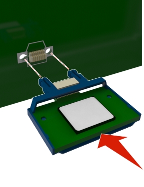
Holding the card by its sides, align the plastic pins (1) on the card with the holes (2) on the controller board.
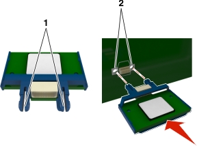
Push the card firmly into place.
| Warning—Potential Damage: Improper installation of the card may cause damage to the card and the controller board. |
| Note: The entire length of the connector on the card must touch and be flush with the controller board. |
The controller board supports one optional Lexmark Internal Solutions Port (ISP).
| Note: This task requires a flat-head screwdriver. |
| | CAUTION—SHOCK HAZARD: If you are accessing the controller board or installing optional hardware or memory devices sometime after setting up the printer, then turn the printer off, and unplug the power cord from the electrical outlet before continuing. If you have any other devices attached to the printer, then turn them off as well, and unplug any cables going into the printer. |
| Warning—Potential Damage: Controller board electronic components are easily damaged by static electricity. Touch a metal surface on the printer before touching any controller board electronic components or connectors. |
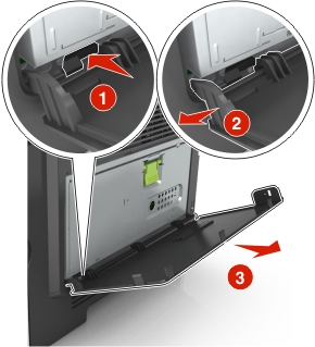
Open the controller board access door.
Lightly press the stop on the left side of the access door, and then slide the access door to remove it.
Unpack the ISP kit.
| Note: Make sure to remove and discard the small cable attached to the white connector. |
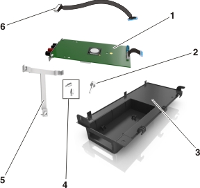
1 | ISP solution |
2 | Screw to attach the ISP to the bracket |
3 | ISP exterior cover |
4 | Screws to attach the ISP metal bracket to the printer cage |
5 | Plastic bracket |
6 | Long ISP cable |
Place the plastic bracket inside the ISP exterior cover until it clicks into place.
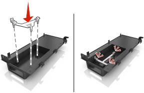
Slide and push the ISP solution into the plastic bracket.
Secure the ISP solution to the plastic bracket using the long screw.
Tighten the two screws on the end of the ISP solution.
Attach the white plug of the ISP solution interface cable into the white receptacle on the ISP.
Attach the ISP exterior cover at an angle by inserting the left hinges first.
Lower the rest of the cover, and then slide the cover to the right.
Run the ISP cable through the controller board shield.
Open the shield using the green handle.
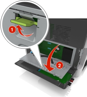
Attach the blue plug of the ISP solution interface cable into the blue receptacle on the controller board.
| Note: If you have installed a printer hard disk, then you need to remove it. For more information, see Removing a printer hard disk. To reinstall the printer hard disk, see Installing a printer hard disk. |
Close the shield.
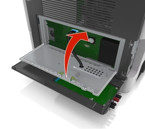
Close the ISP exterior cover.
| Note: When the printer software and any hardware options are installed, it may be necessary to manually add the options in the printer driver to make them available for print jobs. For more information, see Adding available options in the print driver. |
| | CAUTION—SHOCK HAZARD: If you are accessing the controller board or installing optional hardware or memory devices sometime after setting up the printer, then turn the printer off, and unplug the power cord from the electrical outlet before continuing. If you have any other devices attached to the printer, then turn them off as well, and unplug any cables going into the printer. |
| Warning—Potential Damage: Controller board electronic components are easily damaged by static electricity. Touch a metal surface on the printer before touching any controller board electronic components or connectors. |
Access the controller board.
For more information, see Accessing the controller board.
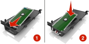
Unpack the printer hard disk.
Install the printer hard disk on the controller board.
| Warning—Potential Damage: Hold only the edges of the printed circuit board assembly. Do not touch or press on the center of the printer hard disk. Doing so may cause damage. |
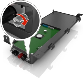
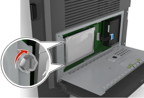
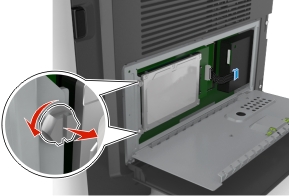
Using a flat-head screwdriver, loosen the screws.
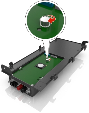
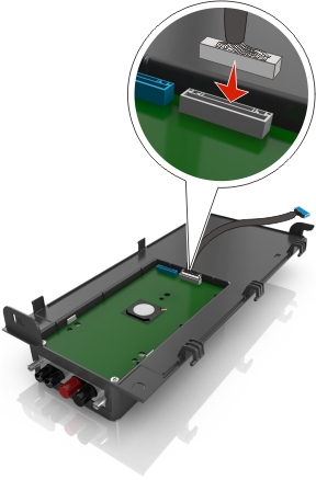
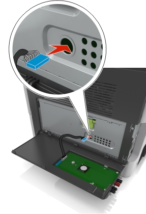
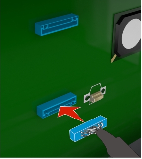
Insert the plug of the printer hard disk interface cable into the receptacle of the controller board.
| Note: The plug and the receptacle are color-coded blue. |
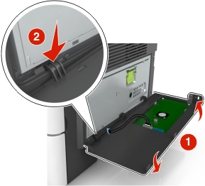
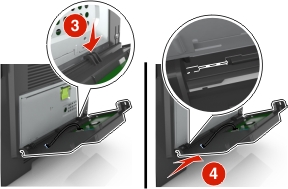
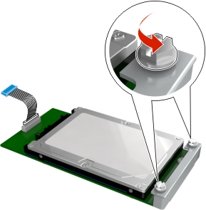
Align the screws on the printer hard disk to the slots on the controller board bracket, and then slide the printer hard disk onto the brackets.
Tighten the two screws.
Close the controller board shield, and then close the controller board access door.
| Note: When the printer software and any hardware options are installed, you may need to manually add the options in the printer driver to make them available for print jobs. For more information, see Adding available options in the print driver. |
| Warning—Potential Damage: Controller board electronic components are easily damaged by static electricity. Touch a metal surface on the printer before touching any controller board electronic components or connectors. |
Access the controller board.
For more information, see Accessing the controller board.
| Note: This task requires a flat-head screwdriver. |
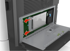
Loosen the screws that connect the printer hard disk to the controller board bracket.
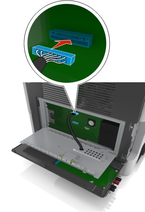
Unplug the printer hard disk interface cable from the receptacle in the controller board, leaving the cable attached to the printer hard disk. To unplug the cable, squeeze the paddle at the plug of the interface cable to disengage the latch before pulling the cable out.

Hold the printer hard disk by the edges, and then remove it from the printer.
Close the controller board shield, and then close the access door.