| | CAUTION—SHOCK HAZARD: If you are accessing the controller board or installing optional hardware or memory devices sometime after setting up the printer, then turn the printer off, and unplug the power cord from the electrical outlet before continuing. If you have any other devices attached to the printer, then turn them off as well, and unplug any cables going into the printer. |
Memory card
DDR2 DIMM
Flash memory
Fonts
Firmware cards
Forms and Bar Code
PRESCRIBE
IPDS
Printer hard disk
LexmarkTM Internal Solutions Ports (ISP)
Standard 10/100/1000 Ethernet
MarkNetTM N8350 802.11 b/g/n wireless print server
MarkNet N8352 802.11 b/g/n wireless print server
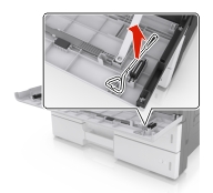
| Note: Use the screwdriver located inside the bottom front door of the printer. |
| | CAUTION—SHOCK HAZARD: If you are accessing the controller board or installing optional hardware or memory devices sometime after setting up the printer, then turn the printer off, and unplug the power cord from the electrical outlet before continuing. If you have any other devices attached to the printer, then turn them off as well, and unplug any cables going into the printer. |
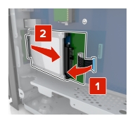
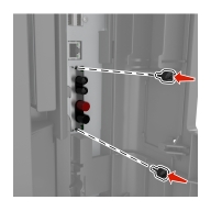
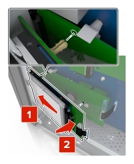
Remove the connector cover.
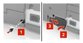
Remove the screws from the controller board access cover.
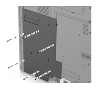
Remove the access cover.
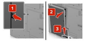
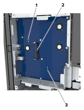
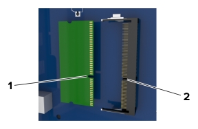
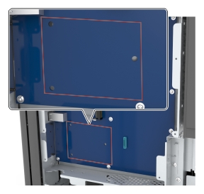
Use the following illustration to locate the appropriate connector:
| Warning—Potential Damage: Controller board electronic components are easily damaged by static electricity. Touch a metal surface on the printer before touching any controller board electronic components or connectors. |
|
1 |
Option card connector |
|
2 |
Memory card connector |
|
3 |
Lexmark Internal Solutions Port or printer hard disk connector |
Align the base of the access cover to the printer.
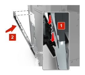
Reattach the access cover.
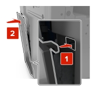
Tighten the screws on the access cover.
Reattach the connector cover.
| | CAUTION—SHOCK HAZARD: If you are accessing the controller board or installing optional hardware or memory devices sometime after setting up the printer, then turn the printer off, and unplug the power cord from the electrical outlet before continuing. If you have any other devices attached to the printer, then turn them off as well, and unplug any cables going into the printer. |
Access the controller board.
For more information, see Accessing the controller board.
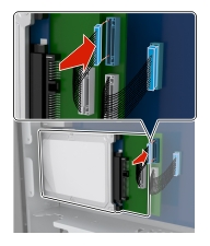
Unpack the memory card.
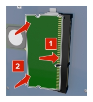
| Warning—Potential Damage: Do not touch the connection points along the edge of the card. Doing so may cause damage. |
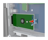
Align the notch (1) on the memory card with the ridge (2) on the connector.
Push the memory card straight into the connector, and then push the card toward the controller board wall until it clicks into place.
| | CAUTION—SHOCK HAZARD: If you are accessing the controller board or installing optional hardware or memory devices sometime after setting up the printer, then turn the printer off, and unplug the power cord from the electrical outlet before continuing. If you have any other devices attached to the printer, then turn them off as well, and unplug any cables going into the printer. |
| Warning—Potential Damage: Controller board electronic components are easily damaged by static electricity. Touch a metal surface on the printer before touching any controller board electronic components or connectors. |
Access the controller board.
For more information, see Accessing the controller board.
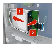
Unpack the optional card.
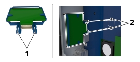
| Warning—Potential Damage: Avoid touching the connection points along the edge of the card. Doing so may cause damage. |
Holding the card by its sides, align the plastic pins (1) on the card with the holes (2) on the controller board.
Push the card firmly into place.
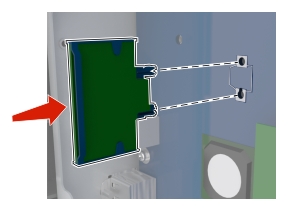
| Warning—Potential Damage: Improper installation of the card may cause damage to the card and the controller board. |
| Note: The entire length of the connector on the card must touch and be flush with the controller board. |
| Note: Use the screwdriver located inside the bottom front door of the printer. |
The controller board supports one optional Lexmark Internal Solutions Port (ISP). Install an ISP for additional connectivity options.
| | CAUTION—SHOCK HAZARD: If you are accessing the controller board or installing optional hardware or memory devices sometime after setting up the printer, then turn the printer off, and unplug the power cord from the electrical outlet before continuing. If you have any other devices attached to the printer, then turn them off as well, and unplug any cables going into the printer. |
| Warning—Potential Damage: Controller board electronic components are easily damaged by static electricity. Touch a metal surface on the printer first before touching any controller board electronic components or connectors. |
Unpack the ISP kit.
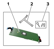
|
1 |
ISP |
|
2 |
Plastic mounting bracket |
|
3 |
Thumbscrews |
Access the controller board. For more information, see Accessing the controller board.
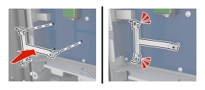
Align the posts of the plastic mounting bracket with the holes on the controller board cage, and then press the bracket on the cage until it clicks into place.
Install the ISP on the bracket.
Use the thumbscrew to attach the bracket to the ISP.
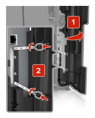
Secure the ISP mounting bracket to the controller board cage using the screws.
Insert the plug of the ISP interface cable into the connector of the controller board.
| Note: Use the screwdriver located inside the bottom front door of the printer. |
| | CAUTION—SHOCK HAZARD: If you are accessing the controller board or installing optional hardware or memory devices sometime after setting up the printer, then turn the printer off, and unplug the power cord from the electrical outlet before continuing. If you have any other devices attached to the printer, then turn them off as well, and unplug any cables going into the printer. |
| Warning—Potential Damage: Controller board electronic components are easily damaged by static electricity. Touch a metal surface on the printer before touching any controller board electronic components or connectors. |
Access the controller board.
For more information, see Accessing the controller board.
Unpack the hard disk.
Locate the appropriate connector on the controller board cage.
| Note: If an optional ISP is installed, then the hard disk must be installed onto the ISP. |
To install a hard disk onto the ISP:
Remove the screws attached to the hard disk mounting bracket, and then remove the bracket.
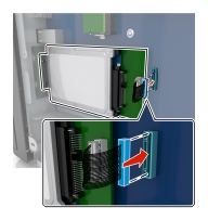
Align the standoffs of the hard disk to the holes in the ISP, and then press the hard disk down until the standoffs are in place.
| Installation warning: Hold the hard disk by its edges. Touching or pressing on the center of the hard disk may damage it. |
Insert the plug of the hard disk interface cable into the receptacle of the ISP.
| Note: The plugs and receptacles are color-coded. |
To install a hard disk directly on the controller board cage:
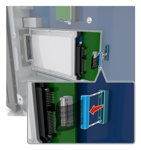
Align the standoffs of the hard disk to the holes in the controller board cage, and then press the hard disk down until the standoffs are in place.
| Installation warning: Hold the hard disk by its edges. Touching or pressing on the center of the hard disk may damage it. |
Use the two provided screws to attach the hard disk mounting bracket.
Insert the plug of the hard disk interface cable into the receptacle of the controller board.
| Note: The plugs and receptacles are color-coded. |
| Note: Use the screwdriver located inside the bottom front door of the printer. |
| | CAUTION—SHOCK HAZARD: If you are accessing the controller board or installing optional hardware or memory devices sometime after setting up the printer, then turn the printer off, and unplug the power cord from the electrical outlet before continuing. If you have any other devices attached to the printer, then turn them off as well, and unplug any cables going into the printer. |
| Warning—Potential Damage: Controller board electronic components are easily damaged by static electricity. Touch a metal surface on the printer before touching any controller board electronic components or connectors. |
Access the controller board.
For more information, see Accessing the controller board.
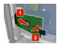
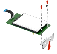
Unplug the hard disk interface cable from the controller board, leaving the cable attached to the hard disk. To unplug the cable, squeeze the paddle at the plug of the interface cable to disengage the latch before pulling out the cable.
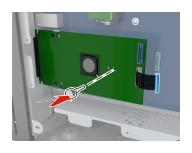
Remove the screws holding the hard disk in place.
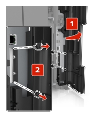
Remove the hard disk.