
| | CAUTION—SHOCK HAZARD: If you are accessing the system board or installing optional hardware or memory devices sometime after setting up the printer, then turn the printer off, and unplug the power cord from the wall outlet before continuing. If you have any other devices attached to the printer, then turn them off as well, and unplug any cables going into the printer. |
Memory cards
Printer memory
Flash memory
Fonts
Firmware cards
Bar Code
IPDS
PrintCryptionTM
Printer hard disk
LexmarkTM Internal Solutions Ports (ISP)
RS-232-C Serial ISP
Parallel 1284-B ISP
MarkNetTM N8250 802.11 b/g/n Wireless ISP
MarkNet N8130 10/100 Fiber ISP
MarkNet N8120 10/100/1000 Ethernet ISP
| Note: An external kit is needed to support the ISP. |
| | CAUTION—SHOCK HAZARD: If you are accessing the system board or installing optional hardware or memory devices sometime after setting up the printer, then turn the printer off, and unplug the power cord from the wall outlet before continuing. If you have any other devices attached to the printer, then turn them off as well, and unplug any cables going into the printer. |
| Note: This task requires a flathead screwdriver. |
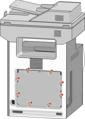
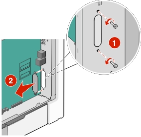
Remove the system board cover.
Turn the screws on the cover counterclockwise to loosen them, but do not remove them.
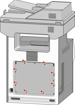
Slide the cover slightly up until each screw is in the keyhole.
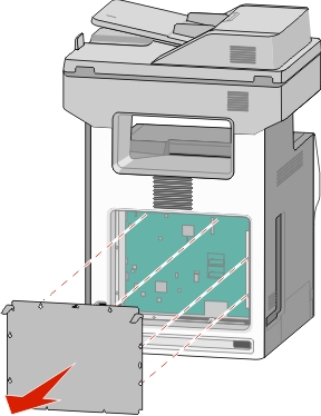
Pull the cover to remove it.
Locate the appropriate connector on the system board.
| Warning—Potential Damage: System board electronic components are easily damaged by static electricity. Touch something metal on the printer before touching any system board electronic components or connectors. |
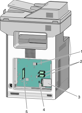
1 | Fax card connector |
2 | Firmware and flash memory card connectors |
3 | Printer hard disk connector |
4 | Internal print server connector |
5 | Memory card connector |
Reattach the system board cover.
| Warning—Potential Damage: System board electronic components are easily damaged by static electricity. Touch something metal on the printer before touching any system board electronic components or connectors. |
Align the keyholes with the screws.
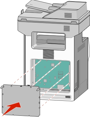
Slide the cover down, and then turn each screw on the cover clockwise to tighten.
| | CAUTION—SHOCK HAZARD: If you are accessing the system board or installing optional hardware or memory devices sometime after setting up the printer, then turn the printer off, and unplug the power cord from the wall outlet before continuing. If you have any other devices attached to the printer, then turn them off as well, and unplug any cables going into the printer. |
| Warning—Potential Damage: System board electronic components are easily damaged by static electricity. Touch something metal on the printer before touching any system board electronic components or connectors. |
An optional memory card can be purchased separately and attached to the system board.
Access the system board.
For more information, see Accessing the system board.
| Note: This task requires a flathead screwdriver. |
Unpack the memory card.
| Warning—Potential Damage: Do not touch the connection points along the edge of the card. Doing so may cause damage. |
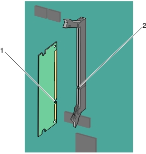
Open the memory card connector latches.
Align the notch (1) on the memory card with the ridge (2) on the connector.
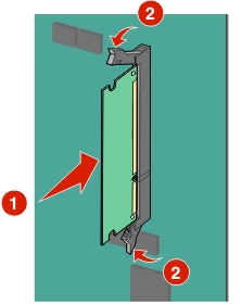
Push the memory card straight into the connector until it clicks into place, and then push the latches to firmly attach the card into the connector.
Reattach the system board cover.
The system board has two connections for an optional flash memory or firmware card. Only one of each may be installed, but the connectors are interchangeable.
| | CAUTION—SHOCK HAZARD: If you are accessing the system board or installing optional hardware or memory devices sometime after setting up the printer, then turn the printer off, and unplug the power cord from the wall outlet before continuing. If you have other devices attached to the printer, then turn them off as well, and unplug any cables going into the printer. |
| Warning—Potential Damage: System board electronic components are easily damaged by static electricity. Touch something metal on the printer before touching any system board electronic components or connectors. |
| Note: This task requires a flathead screwdriver. |
Access the system board.
For more information, seeAccessing the system board.
Unpack the card.
| Warning—Potential Damage: Avoid touching the connection points along the edge of the card. |
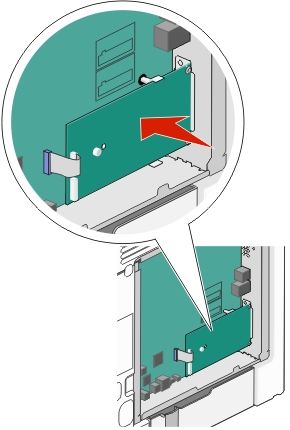
Holding the card by its sides, align the plastic pins (1) on the card with the holes (2) on the system board.
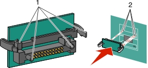
Push the card firmly into place.
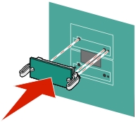
| Warning—Potential Damage: Be careful not to damage the connectors. |
| Note: The entire length of the connector on the card must touch and be flush against the system board. |
Reattach the system board cover.
| Note: When the printer software and any options are installed, it may be necessary to manually add the options in the printer driver to make them available for print jobs. For more information, see Adding available options in the print driver. |
The system board supports one optional Lexmark Internal Solutions Port (ISP).
| | CAUTION—SHOCK HAZARD: If you are accessing the system board or installing optional hardware or memory devices sometime after setting up the printer, then turn the printer off, and unplug the power cord from the wall outlet before continuing. If you have any other devices attached to the printer, then turn them off as well, and unplug any cables going into the printer. |
| Warning—Potential Damage: System board electronic components are easily damaged by static electricity. Touch something metal on the printer before touching any system board electronic components or connectors. |
Access the system board.
For more information, see Accessing the system board.
| Note: This task requires a flathead screwdriver. |
Unpack the ISP kit.
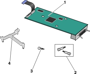
1 | ISP solution |
2 | Screws for the ISP solution |
3 | Screw for the plastic bracket |
4 | Plastic bracket |
Locate the appropriate holes on the system board where the posts of the plastic tee will be aligned.
| Note: If an optional printer hard disk is currently installed, then remove it first. For more information, see Removing a printer hard disk. |
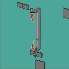
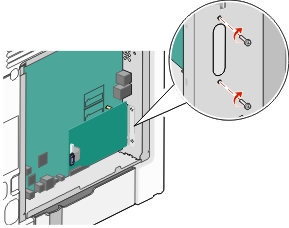
Remove the screws, and then remove the metal cover from the ISP opening.
Attach the ISP solution to the system board.
Align the posts of the plastic tee to the holes on the system board.
Hold the edges of the ISP and guide it to the opening on the system board cage, and then gently allow it to rest on the plastic tee.
Use the provided screw to attach the plastic bracket to the ISP solution.
Connect the ISP solution interface cable into the color-coded receptacle on the system board.
Firmly connect the ISP solution to the system board cage using the two screws.
Reattach the system board cover.
| Note: If you have removed an optional printer hard disk while installing the Internal Solutions Port, then reinstall the printer hard disk first before reattaching the system board cover. For more information, see Installing a printer hard disk. |
| | CAUTION—SHOCK HAZARD: If you are accessing the system board or installing optional hardware or memory devices sometime after setting up the printer, then turn the printer off, and unplug the power cord from the wall outlet before continuing. If you have any other devices attached to the printer, then turn them off as well, and unplug any cables going into the printer. |
| Warning—Potential Damage: System board electronic components are easily damaged by static electricity. Touch something metal on the printer before touching any system board electronic components or connectors. |
Access the system board.
For more information, see Accessing the system board.
| Note: This task requires a flathead screwdriver. |
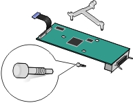
Unpack the printer hard disk.
Locate the appropriate holes on the system board where the posts of the plastic tee will be aligned.
| Note: If an optional ISP is currently installed, then the printer hard disk must be installed onto the ISP. |
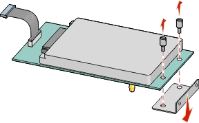
Using a flathead screwdriver, loosen the screws.
Remove the screws attached to the printer hard disk mounting bracket, and then remove the bracket.
Install the printer hard disk onto the ISP:
Hold the edges of the printed circuit board assembly, and then align the standoffs of the printer hard disk to the holes in the ISP.
Press down on the printer hard disk until the standoffs are in place.
| Warning—Potential Damage: Do not press on the center of the printer hard disk. Doing so may cause damage to the hard disk. |
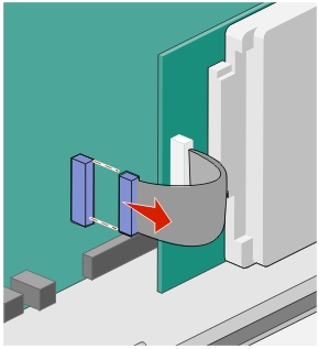
Insert the plug of the printer hard disk interface cable into the receptacle of the ISP.
| Note: The plugs and receptacles are color-coded. |
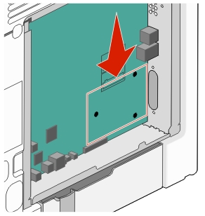
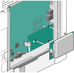
Hold the edges of the printed circuit board assembly, and then align the standoffs of the printer hard disk to the holes in the system board. Press down on the printer hard disk until the standoffs are in place.
| Warning—Potential Damage: Do not press on the center of the printer hard disk. Doing so may cause damage to the hard disk. |
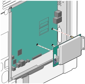
Use the two provided screws to attach the printer hard disk mounting bracket.

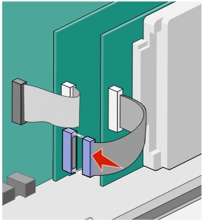
Insert the plug of the printer hard disk interface cable into the receptacle of the system board.
| Note: The plugs and receptacles are color-coded. |
Reattach the system board cover.
| Warning—Potential Damage: System board electronic components are easily damaged by static electricity. Touch something metal on the printer before touching any system board electronic components or connectors. |
Access the system board.
For more information, see Accessing the system board.
| Note: This task requires a flathead screwdriver. |
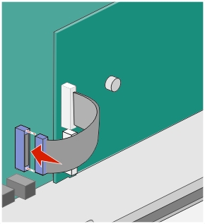
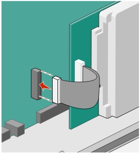
Unplug the printer hard disk interface cable from the system board, leaving the cable attached to the printer hard disk. To unplug the cable, squeeze the paddle at the plug of the interface cable to disengage the latch before pulling the cable out.
Remove the screws that connect the printer hard disk to the system board cage.
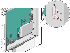
Remove the printer hard disk by pulling it upward to unseat the standoffs.
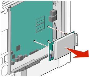
Set the printer hard disk aside.
Reattach the system board cover.